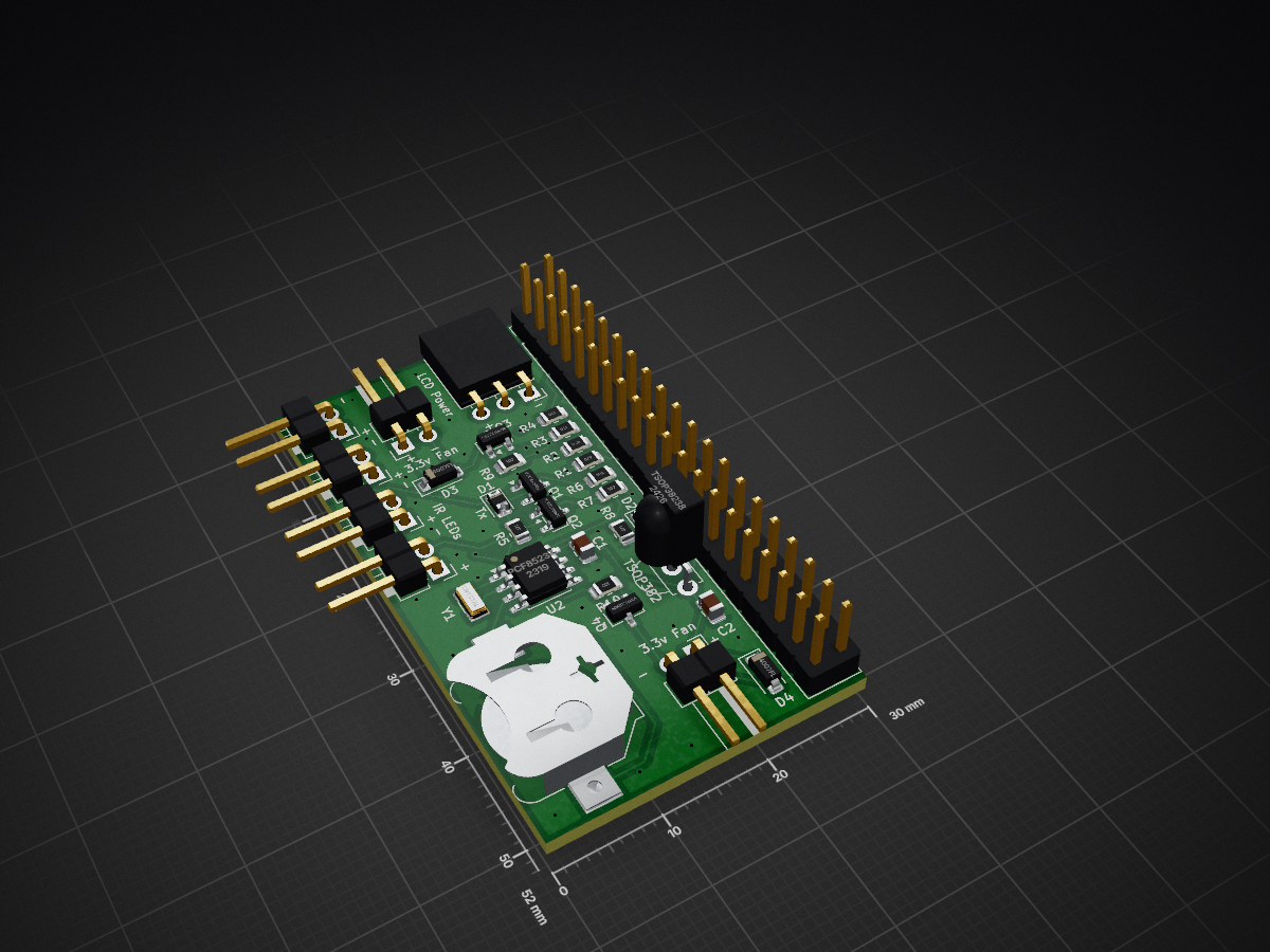
Raspi ir is an open-source printed circuit board by custom-ds, from the custom-ds/Universal-Remote-LIRC repository on GitHub, published under the GPL-3.0 licence. It is a 2-layer board of 30 × 52 mm with 32 parts on 52 nets, routed with 208 tracks and 40 vias.
It is built around the PCF8523T, TSOP38238 and HR3P-N4EC-00000, with the MMBT2222A and 1N4007FL among its other parts. Its parts include 10 resistors, 8 connectors, 4 diodes, 4 transistors and 2 capacitors.
Display is based on the Raspberry Pi Touch Display 2, which is a 720x1280 pixels.
Installing on a Pi
There is an installation script that handles most of the setup on the Raspberry Pi.
Use the Raspberry Pi Imager to install the base load of Raspberry Pi OS. This has been tested on a Pi 3 and Pi 4.
Install the 64 bit version of the operating system.
Set the time zone and keyboard layout as appropriate.
Set a hostname
Add a username, and set a password on it.
Configure the Wifi network.
Enable SSH access with password authentication.
Write out the image to the MicroSD card. Insert the card into the Raspberry Pi, then complete the assembly of the screen to the Pi. Attach the Pi daughter board to interface off to the
Be sure to include the power cable as well as the ribbon cable. Attach the
Once assembly is completed, boot the Pi up
SSH into the new Pi computer using another PC. Update the core operating system before proceeding.
You should be able to test the IR receiver. The basic form of that is to use the mode2 program to read in the gaps between the pulses and spaces.
mode2 -d /dev/lirc0
Note that it is possible that the devices have been created in other orders, and you may need to modify the device with something like mode2 -d /dev/lirc1. Check the /dev/ directory for possible options.
ls /dev/lirc*
Screen Configuration
Resolution will automatically set, but the rotation angle needs to be corrected for the portrait mode.
Inside of the Raspbian GUI, go to Preferences -> Screen Configuration. Select DSI-1 from the screens list, and drill into Orientation and select Right.
Click the Apply button, and the confirm the change.
The GUI runs as a daemon that will automatically start when the Pi boots up. If the script crashes for any reason, the daemon will automatically restart itself.
Copy the remote.service file into /etc/systemd/system/ folder.
Most of the mainstream remotes can be found in the LIRC repositories around the Internet, but certain less-known remotes either aren't there, or are hidden among random names of companies that might not even be around anymore.
To record, you'll use the Infrared Receiver, along with the irrecord program. irrecord will guide you through the process, which basically involves starting the recording, then pushing the buttons on the remote enough times that it generates templates of the various sequences.
Before you get started though, you should be aware of the standard naming convention for the key presses. It's possible to rename these outstand of the standards, but that requires an extra switch. To get the full list of possible buttons, type:
irrecord --list-namespace
To start recording, type irrecord -d /dev/lirc0 myRemote.conf and follow the prompts, where myRemote is a descriptive name of the specific remote or product that you are recording for.
Once it is finished recording, move the resulting .conf file into /etc/lirc/lircd.conf.d/, then restart the lirc services.
systemctl restart lircd
You should be able to see the new remote when you list the remotes.
irsend LIST "" ""
Then you can list the specific buttons available for the new remote, by listing that configuration.
It measures 30 × 52 mm and has 2 copper layers, 1.6 mm thick.
What parts does the Raspi ir use?
32 parts, built around the PCF8523T, TSOP38238, HR3P-N4EC-00000 and MMBT2222A. The full list of its parts is on this page, with links to each part's symbol and footprint where PCBKit's library has them.
Where can I download the Raspi ir KiCad files?
From the custom-ds/Universal-Remote-LIRC repository on GitHub, at the commit this page was made from: the board is PCB/raspi-ir/raspi-ir.kicad_pcb and its schematic PCB/raspi-ir/raspi-ir.kicad_sch. PCBKit opens the board in the browser, with nothing to install.
Can I use the Raspi ir design in my own project?
Its repository publishes it under the GPL-3.0 licence: you may reuse it on that licence's terms (keep the author's notice, and for a copyleft licence share your changes alike).
With the Arduion programmer board loaded with the jtag2updi software, and the Pin 6 from the Arduino connected to the Reset line on the ATTiny404, you can Build and Program directly inside of the Visual Studio Code.