PowerDistributionPCB
CUSail-Navigation/PCB-FA25-SP26
This is a repository containing the PCBs designed during the FA25-SP26 academic year. Due to high compatibility and relative ease of use, all of these files are made with KiCad.

This is a repository containing the PCBs designed during the FA25-SP26 academic year. Due to high compatibility and relative ease of use, all of these files are made with KiCad.
Switchbox is an open-source printed circuit board by CUSail-Navigation, from the CUSail-Navigation/PCB-FA25-SP26 repository on GitHub. It is a 4-layer board of 90 × 68 mm with 38 parts on 67 nets, routed with 194 tracks and 35 vias.
Its parts include 9 resistors, 7 capacitors, 6 diodes, 6 switches and 1 IC. It belongs with the AVR (ATmega, ATtiny) boards of this library.
Here are the files for the three main PCBs designed during the FA25-SP26 academic year. These were all designed with KiCad due to its support across all operating systems and our use cases not requiring more sophisticated PCB design tools.
These PCBs were designed with the idea that the boat would contain two electronics boxes - one for digital electronics, and the other for power electronics. The decision to split them was made because it is unlikely that one would need to work on both simultaneously (thus making the electronics physically easier to work with), reduces cable clutter, and reduces the likelihood of every part of the system getting drenched in water in the event that the boat capsizes.
This PCB houses the digital electronics found on the boat. This includes the main microcontroller(s), sensors, radio transmitters/recievers, and interfaces to other parts of the boat which rely on computations. This PCB sits in the digital electronics box.
This PCB contains the circuitry necessary for stepping down and distributing power supplied from our 22.2V LiPo battery. This PCB sits in the power electronics box.
Because we use a LiPo battery, battery failure is possible of the battery discharges too much. This PCB is responsible for monitoring the state of the battery and cutting power in the event that it discharges too much. This PCB is housed in the power electronics box.
| Qty | Value | Footprint | References |
|---|---|---|---|
| 6 | 680 | Resistor_SMD:R_0805_2012Metric_Pad1.20x1.40mm_HandSolder | R1, R2, R3, R4, R5, R6 |
| 6 | LED | switchbox_footprints:2_pin_header | D1, D2, D3, D4, D5, D6 |
| 5 | LOGO | LOGO | G***, G***, G***, G***, G*** |
| 4 | SW_SPDT | switchbox_footprints:3_pin_header | SW1, SW2, SW3, SW4 |
| 2 | 22 uF | switchbox_footprints:CAPC3216X190N | C3, C4 |
| 1 | 0.1 uF | switchbox_footprints:CAPC0603X33N | C7 |
| 1 | 0.1µF | switchbox_footprints:CAPC0603X33N | C5 |
| 1 | 10 uF | switchbox_footprints:CAPC1005X70N | C1 |
| 1 | 100 nF | Capacitor_SMD:C_0603_1608Metric_Pad1.08x0.95mm_HandSolder | C2 |
| 1 | 10K | Resistor_SMD:R_0805_2012Metric_Pad1.20x1.40mm_HandSolder | R7 |
| 1 | 10k | Resistor_SMD:R_0805_2012Metric_Pad1.20x1.40mm_HandSolder | R11 |
| 1 | 20k | Resistor_SMD:R_0805_2012Metric_Pad1.20x1.40mm_HandSolder | R10 |
| 1 | 3.9 uH | switchbox_footprints:IND_BOURNS_SRR5018 | L1 |
| 1 | 47µF | switchbox_footprints:CAPC2012X145N | C6 |
| 1 | 484050003 | switchbox_footprints:usba_footprint | J2 |
| 1 | AP63203WU-7 | switchbox_footprints:buck | U1 |
| 1 | Arduino_Nano_v3.x | Module:Arduino_Nano | A2 |
| 1 | SW_SPDT_BOX | switchbox_footprints:3_pin_header | SW6 |
| 1 | SW_SPST_LED | switchbox_footprints:4_pin_header | SW5 |
| 1 | ~ | switchbox_footprints:xbee | XBEE1 |
It measures 90 × 68 mm and has 4 copper layers, 1.6 mm thick.
38 parts. The full list of its parts is on this page, with links to each part's symbol and footprint where PCBKit's library has them.
From the CUSail-Navigation/PCB-FA25-SP26 repository on GitHub, at the commit this page was made from: the board is Switchbox/Switchbox.kicad_pcb. PCBKit opens the board in the browser, with nothing to install.
Its repository states no licence, so its author keeps all rights: ask CUSail-Navigation before reusing the design.

CUSail-Navigation/PCB-FA25-SP26
This is a repository containing the PCBs designed during the FA25-SP26 academic year. Due to high compatibility and relative ease of use, all of these files are made with KiCad.

CUSail-Navigation/PCB-FA25-SP26
This is a repository containing the PCBs designed during the FA25-SP26 academic year. Due to high compatibility and relative ease of use, all of these files are made with KiCad.

CUSail-Navigation/PCB-FA25-SP26
This is a repository containing the PCBs designed during the FA25-SP26 academic year. Due to high compatibility and relative ease of use, all of these files are made with KiCad.

CUSail-Navigation/PCB-FA25-SP26
This is a repository containing the PCBs designed during the FA25-SP26 academic year. Due to high compatibility and relative ease of use, all of these files are made with KiCad.

CUSail-Navigation/PCB-FA25-SP26
This is a repository containing the PCBs designed during the FA25-SP26 academic year. Due to high compatibility and relative ease of use, all of these files are made with KiCad.


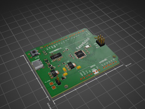
Hanqaqa/Easyduino
Easily dive into different PCB KiCad designs of the most popular microcontroller devboards

murexrobotics/electrical
Highly integrated electronics design and printed circuit boards (PCBs) for the MATE ROV Competition. Attempt the impossible.


magnusnordlander/smart-lcc
A smarter LCC for the Lelit Bianca V2, with Wi-Fi and stuff.

Roboy/HTC_Vive_Sensors
Schematics and PCB designs for our custom Vive sensors based on a quad op-amp chip rather than discrete transistors.

sparkfun/SparkFun_RTK_Facet
The hardware and enclosure for the popular centimeter level RTK Facet GNSS receiver with built in display.