2 layers160 × 100 mm
CountingPRU v2-3
lnls-sirius/counting-pru
Multi-purpose counting system based on Beaglebone Black PRU
94 parts

 cruunnerr/CrallyBoard
Smart Home System / Alarm System / Input Output System for Raspberry Pi CM4
Cam server is an open-source printed circuit board by cruunnerr, from the cruunnerr/CrallyBoard repository on GitHub. It is a 2-layer board of 180.7 × 143.8 mm with 231 parts on 383 nets, routed with 3,776 tracks and 336 vias.
It is built around the AP22653W6, FSUSB42MUX and ICL7665S, with the DF01S-T, ZPY7.5 and BC337 among its other parts. Its parts include 45 resistors, 44 capacitors, 23 diodes, 20 connectors and 13 ICs. It belongs with the computers and single-board computers boards and the Raspberry Pi (Linux) boards of this library.


Smart Home System / Alarm System / Input Output System for Raspberry Pi CM4
THIS IS JUST A DOCUMENTATION FOR MYSELF! YOU CAN USE IT, BUT THERE MAY BE MISSING SOME STEPS!
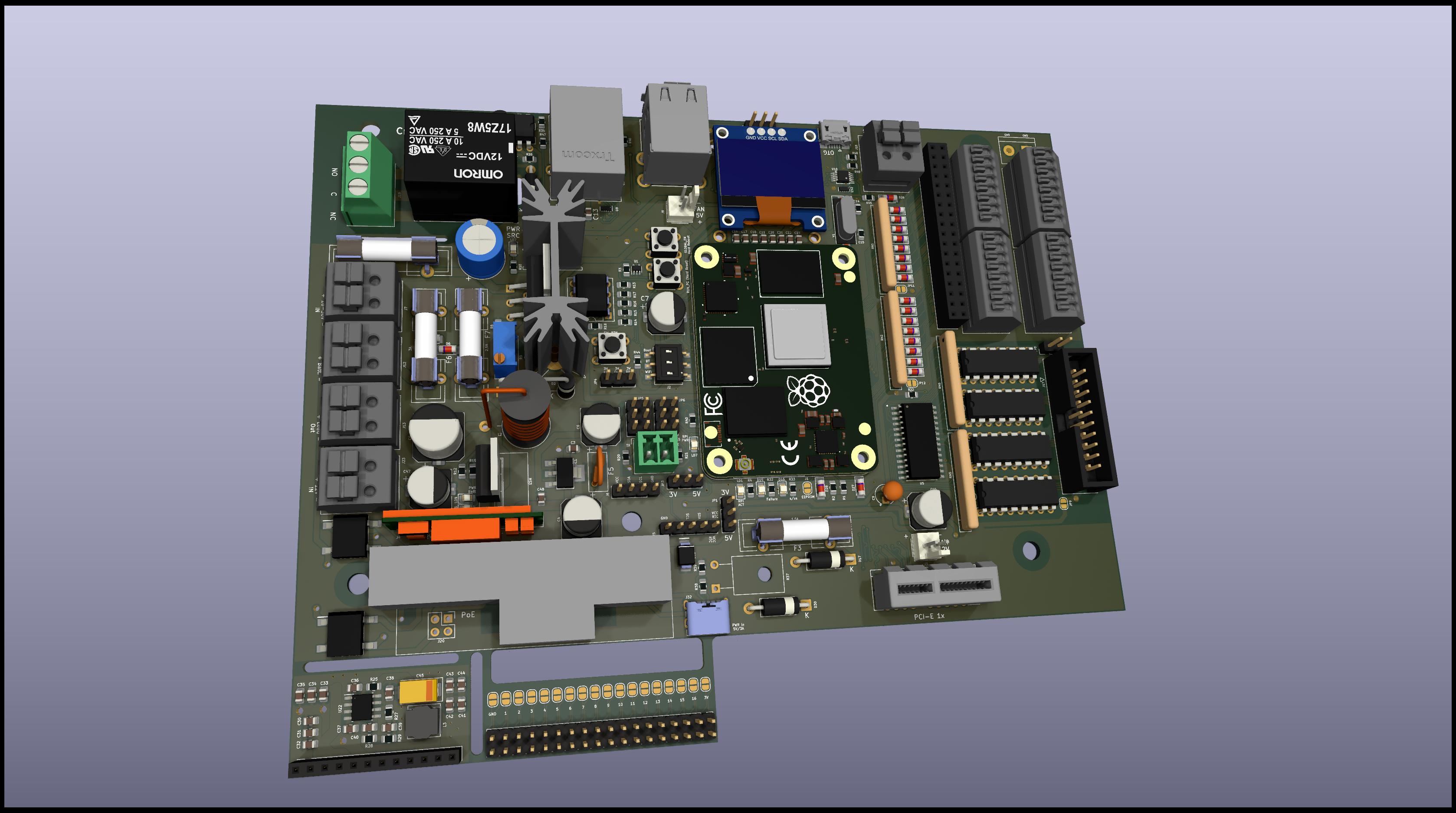
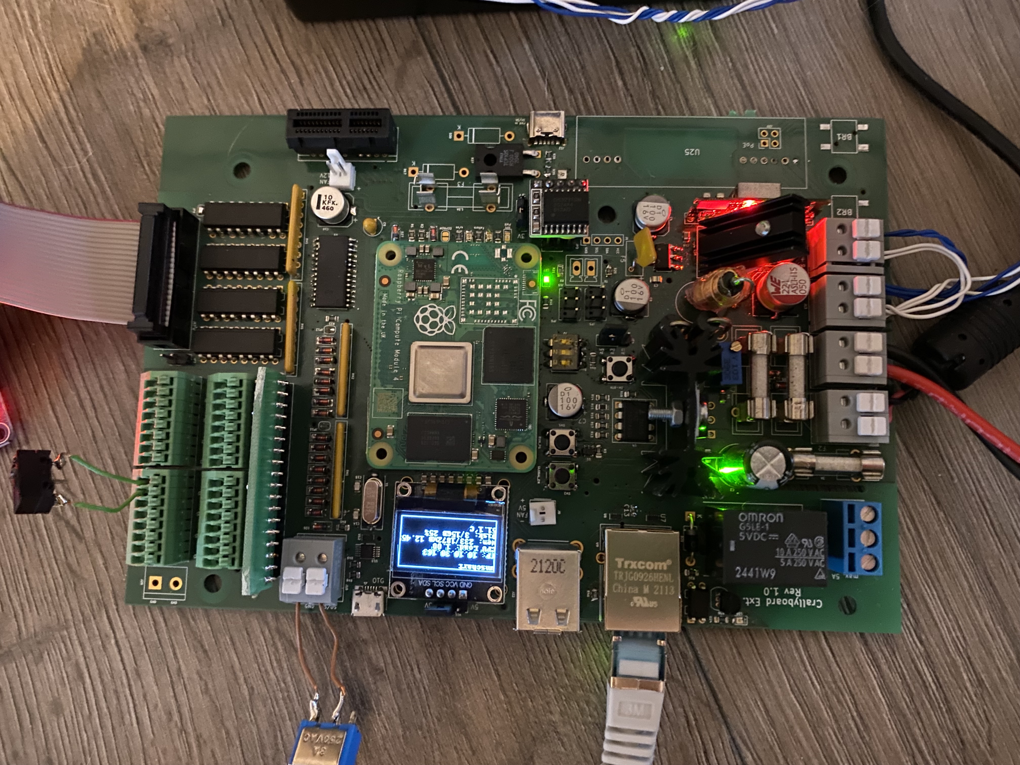
This is a custom Board made for Raspberry Pi CM4 Module
It contains:
Main Supply Power:
There yre several Options:
When using 16-30V Power Supply you were able to connect a Gel Lead Battery. With the potentiometer you can adjust the Battery Load Voltage (max. 15V due to Zener Diodes). Also there is a deep discharge protection via ICL7665. It disconnects the Output from Battery at around <11,2V and reconnects at around >13V.
Well, the values are not that accurate and I know that the circuit maybe isn't the best solution. But for my usage it's working well enough.
For the 3V Line on the board you can choose (via jumper) to use the 3V comming from the RPi or use a seperate regulator (TL1963A-33DCYR).
Power Consumption:
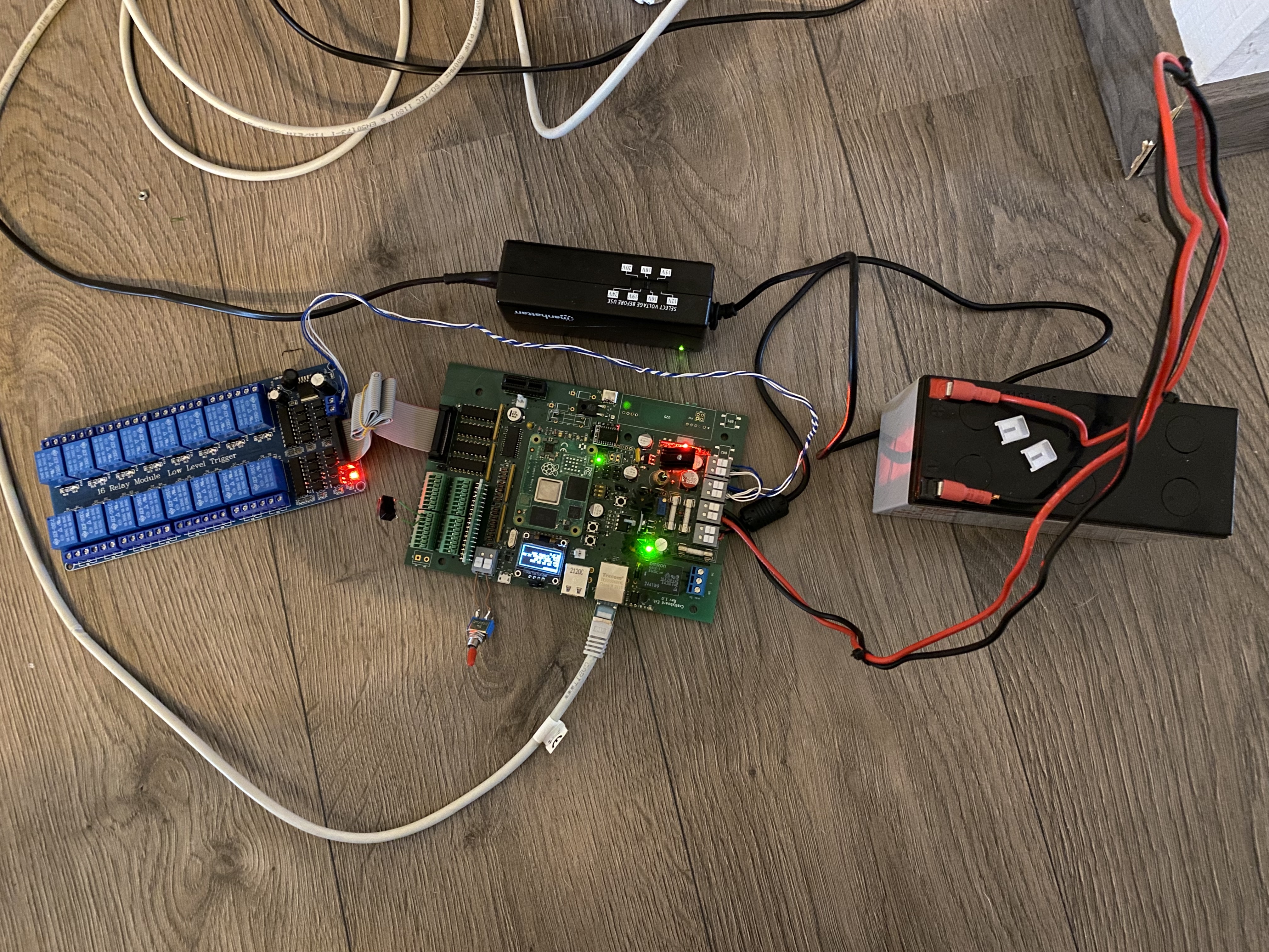
When RPi, SSD1306 and DS3231 is on Board and no Relais is activ we are around = 3,8W (12,9V*0,3A)
With all Relays on Ralay Board activ we are around = 14W
So every Relay consumes around 0,6W or 0,05A
So with no Relay activ and just using the RPi with OLED and RTC we get the following runtimes:
7Ah Battery = >20h
17Ah Battery = >50h
24Ah Battery = >75h
I personally use it as Smart Home System and Alarm System. The Software is written with python and php. Maybe I will add it to the repository later...
| Qty | Value | Footprint | References |
|---|---|---|---|
| 21 | Jumper_2_Bridged | Jumper:SolderJumper-2_P1.3mm_Open_RoundedPad1.0x1.5mm | JP11, JP12, JP13, JP14, JP15, JP16, JP17, JP18, JP19, JP20, JP21, JP22, JP23, JP24, JP25, JP26 +5 |
| 19 | 1N47xxA | Diode_SMD:D_MiniMELF | D10, D11, D12, D13, D14, D18, D19, D20, D21, D22, D23, D24, D25, D26, D27, D28 +3 |
| 12 | 10u | Capacitor_SMD:C_0805_2012Metric | C16, C17, C24, C26, C27, C28, C29, C41, C42, C43, C44, C46 |
| 9 | 100n | Capacitor_SMD:C_0805_2012Metric | C13, C18, C19, C20, C21, C22, C23, C36, C37 |
| 8 | 1k | Resistor_SMD:R_0805_2012Metric_Pad1.20x1.40mm_HandSolder | R4, R14, R22, R26, R36, R40, R44, R45 |
| 6 | 10u 35v | Capacitor_SMD:C_0805_2012Metric | C30, C31, C32, C33, C34, C35 |
| 5 | MountingHole_4.3mm_M4 | MountingHole:MountingHole_4.3mm_M4 | H1, H2, H3, H4, H5 |
| 5 | Screw_Terminal_01x02 | TerminalBlock_WAGO:TerminalBlock_WAGO_804-102_1x02_P5.00mm_45Degree | J7, J12, J13, J18, J23 |
| 4 | 36K 1% | Resistor_SMD:R_0805_2012Metric | R50, R51, R52, R54 |
| 4 | 3k3 | Resistor_SMD:R_0805_2012Metric_Pad1.20x1.40mm_HandSolder | R1, R2, R20, R21 |
| 4 | Jumper_3_Bridged12 | Connector_PinHeader_2.54mm:PinHeader_1x03_P2.54mm_Vertical | JP1, JP2, JP3, JP4 |
| 4 | PC847 | Package_DIP:DIP-16_W7.62mm | U18, U19, U20, U21 |
| 4 | Screw_Terminal_01x08 | aaaa:250-408 | J14, J16, J26, J27 |
| 3 | Button_Switch_THT:SW_PUSH_6mm_H5mm | SW1, SW2, SW3 | |
| 3 | 100uF/ 16V | Capacitor_SMD:CP_Elec_8x6.2 | C4, C7, C8 |
| 3 | 2,2k | Resistor_SMD:R_0805_2012Metric_Pad1.20x1.40mm_HandSolder | R10, R12, R19 |
| 3 | 2.2K 1% | Resistor_SMD:R_0805_2012Metric | R29, R48, R49 |
| 3 | TPD4EUSB30 | Package_SON:USON-10_2.5x1.0mm_P0.5mm | U7, U8, U12 |
| 2 | 100uF | Capacitor_Tantalum_SMD:CP_EIA-7343-31_Kemet-D | C25, C45 |
| 2 | 10k | Resistor_SMD:R_0805_2012Metric_Pad1.20x1.40mm_HandSolder | R16, R18 |
| 2 | 12K 1% | Resistor_SMD:R_0805_2012Metric | R28, R30 |
| 2 | 20k | Resistor_THT:R_Array_SIP9 | RN1, RN2 |
| 2 | 27pF | Resistor_SMD:R_0805_2012Metric | C14, C15 |
| 2 | 330R | Resistor_THT:R_Array_SIP9 | RN5, RN6 |
| 2 | 3A | Fuse_Holders_and_Fuses:Fuseholder5x20_horiz_open_lateral_Type-II | F2, F6 |
| 2 | 470R | Resistor_SMD:R_0805_2012Metric | R46, R47 |
| 2 | 470R | Resistor_SMD:R_0805_2012Metric_Pad1.20x1.40mm_HandSolder | R32, R33 |
| 2 | 5,1k | Resistor_SMD:R_0805_2012Metric_Pad1.20x1.40mm_HandSolder | R38, R39 |
| 2 | Conn_02x03_Odd_Even | Connector_PinHeader_2.54mm:PinHeader_2x03_P2.54mm_Vertical | JP5, JP6 |
| 2 | DF01S-T | aaaa:SOP510P1040X293-4N | BR1, BR2 |
| 2 | FAN | Connector_Molex:Molex_KK-254_AE-6410-02A_1x02_P2.54mm_Vertical | J3, J9 |
| 2 | ZPY7.5 | Diode_SMD:D_MiniMELF | D5, D6 |
| 2 | nf | Resistor_SMD:R_0805_2012Metric | R31, R34 |
| 2 | nf | Capacitor_SMD:C_0805_2012Metric | C38, C40 |
| 1 | 0,1uF | Capacitor_THT:CP_Radial_Tantal_D4.5mm_P2.50mm | C9 |
| 1 | 0,5R | Package_TO_SOT_THT:TO-126-2_Horizontal_TabUp | R37 |
| 1 | 1,5A | Fuse_Holders_and_Fuses:Fuseholder5x20_horiz_open_lateral_Type-II | F3 |
| 1 | 1.2nF | Capacitor_SMD:C_0805_2012Metric | C39 |
| 1 | 100k | Resistor_SMD:R_0805_2012Metric_Pad1.20x1.40mm_HandSolder | R13 |
| 1 | 100nF/ 16V | Capacitor_SMD:C_0805_2012Metric | C3 |
| 1 | 100uF/ 50V | Capacitor_SMD:CP_Elec_8x6.2 | C47 |
| 1 | 10R | Resistor_SMD:R_0805_2012Metric | R25 |
| 1 | 10uF | Capacitor_SMD:CP_Elec_8x6.2 | C10 |
| 1 | 12K 1% | Capacitor_SMD:C_0805_2012Metric | R53 |
| 1 | 137k | Resistor_SMD:R_0805_2012Metric_Pad1.20x1.40mm_HandSolder | R15 |
| 1 | 15K 1% | Capacitor_SMD:C_0805_2012Metric | R55 |
| 1 | 1N4007 | Diode_THT:D_DO-41_SOD81_P10.16mm_Horizontal | D29 |
| 1 | 2,5A | Fuse_Holders_and_Fuses:Fuseholder5x20_horiz_open_lateral_Type-II | F7 |
| 1 | 20K 1% | Resistor_SMD:R_0805_2012Metric | R27 |
| 1 | 220R | Resistor_SMD:R_0805_2012Metric_Pad1.20x1.40mm_HandSolder | R3 |
| 1 | 220uF | Capacitor_SMD:CP_Elec_10x10 | C6 |
| 1 | 22u/10V | Capacitor_SMD:C_0805_2012Metric | C48 |
| 1 | 24MHz | Crystal:Crystal_SMD_HC49-SD | Y1 |
| 1 | 330R | Resistor_SMD:R_0805_2012Metric_Pad1.20x1.40mm_HandSolder | R35 |
| 1 | 33uH | Inductor_THT:L_Axial_L26.0mm_D10.0mm_P7.62mm_Vertical_Fastron_77A | L2 |
| 1 | 470uF | Capacitor_THT:CP_Radial_D10.0mm_P5.00mm | C2 |
| 1 | 690-008-221-904 | CM4IO:MOLEX_USB_67298-4090 | J22 |
| 1 | 74LVC1G07_copy | Package_TO_SOT_SMD:SOT-353_SC-70-5 | U1 |
| 1 | 750k | Resistor_SMD:R_0805_2012Metric_Pad1.20x1.40mm_HandSolder | R17 |
| 1 | 820R | Resistor_SMD:R_0805_2012Metric_Pad1.20x1.40mm_HandSolder | R6 |
| 1 | AG5300 bzw. AG5400 | aaaa:AG5300 | U25 |
| 1 | AP22653W6 | Package_TO_SOT_SMD:SOT-23-6 | U13 |
| 1 | AP64501SP-13 | Package_SO:SOIC-8-1EP_3.9x4.9mm_P1.27mm_EP2.95x4.9mm_Mask2.71x3.4mm_ThermalVias | U22 |
| 1 | Act_LED | LED_SMD:LED_0805_2012Metric_Pad1.15x1.40mm_HandSolder | LD7 |
| 1 | BC337 | Package_TO_SOT_THT:TO-92_Inline | Q2 |
| 1 | ComputeModule4-CM4 | CM4IO:Raspberry-Pi-4-Compute-Module | Module1 |
| 1 | Conn_01x02 | TerminalBlock:TerminalBlock_bornier-2_P5.08mm | J29 |
| 1 | Conn_01x02 | Jumper:SolderJumper-2_P1.3mm_Open_RoundedPad1.0x1.5mm | J1 |
| 1 | Conn_01x04 | Connector_PinHeader_2.54mm:PinHeader_1x04_P2.54mm_Vertical | J6 |
| 1 | Conn_01x12_Male | Connector_PinSocket_2.54mm:PinSocket_1x12_P2.54mm_Vertical | J28 |
| 1 | Conn_02x03_Counter_Clockwise | Button_Switch_SMD:SW_DIP_SPSTx03_Slide_Omron_A6S-310x_W8.9mm_P2.54mm | J2 |
| 1 | Conn_02x10_Odd_Even | Connector_IDC:IDC-Header_2x10_P2.54mm_Vertical | J17 |
| 1 | Conn_02x18_Odd_Even | Connector_PinSocket_2.54mm:PinSocket_2x18_P2.54mm_Vertical | J30 |
| 1 | Conn_02x18_Odd_Even | Connector_PinHeader_2.54mm:PinHeader_2x18_P2.54mm_Vertical | J31 |
| 1 | D_Zener | Diode_THT:D_DO-15_P12.70mm_Horizontal | D30 |
| 1 | FSUSB42MUX | Package_SO:MSOP-10_3x3mm_P0.5mm | U10 |
| 1 | G5LE-1 | Relay_THT:Relay_SPDT_Omron-G5LE-1 | K1 |
| 1 | Heatsink | manuelLIB:Heatsink_SK95 | HS3 |
| 1 | Heatsink | Heatsink:Heatsink_Fischer_SK104-STC-STIC_35x13mm_2xDrill2.5mm | HS2 |
| 1 | ICL7665 | Package_DIP:DIP-8_W7.62mm_Socket | U4 |
The 198 most common of 231 parts.
lnls-sirius/counting-pru
Multi-purpose counting system based on Beaglebone Black PRU


NBence0/JedlikBots
Welcome to the official GitHub page of JedlikBots! 🎓🤖 We are the dedicated team of software development and robotics students from the Jedlik Ányos Technical School in Győr, Hungary.

It measures 180.7 × 143.8 mm and has 2 copper layers, 1.68 mm thick.
231 parts, built around the AP22653W6, FSUSB42MUX, ICL7665S and DF01S-T. The full list of its parts is on this page, with links to each part's symbol and footprint where PCBKit's library has them.
From the cruunnerr/CrallyBoard repository on GitHub, at the commit this page was made from: the board is kicad files/cam_server.kicad_pcb and its schematic kicad files/cam_server.kicad_sch. PCBKit opens the board in the browser, with nothing to install.
Its repository states no licence, so its author keeps all rights: ask cruunnerr before reusing the design.