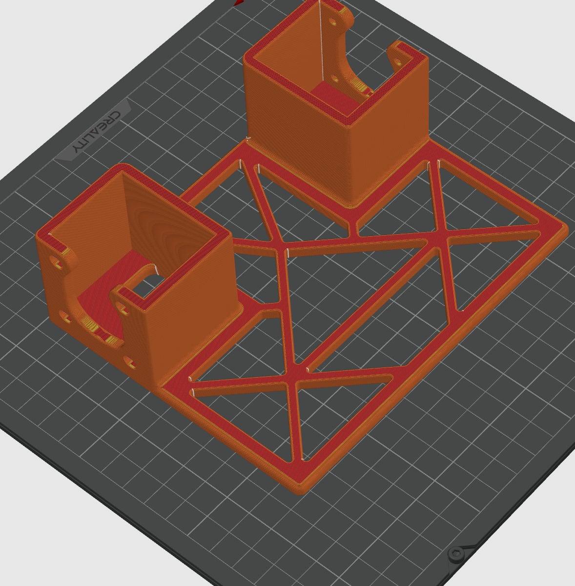
6 layers120.1 × 70.2 mm
Felső panel
NBence0/JedlikBots
Welcome to the official GitHub page of JedlikBots! 🎓🤖 We are the dedicated team of software development and robotics students from the Jedlik Ányos Technical School in Győr, Hungary.
283 parts

 NBence0/JedlikBots
Welcome to the official GitHub page of JedlikBots! 🎓🤖 We are the dedicated team of software development and robotics students from the Jedlik Ányos Technical School in Győr, Hungary.
CM5IO második terv is an open-source printed circuit board by NBence0, from the NBence0/JedlikBots repository on GitHub. It is a 6-layer board of 155 × 100 mm with 491 parts on 650 nets, routed with 253 tracks and 33 vias.
It is built around the 74HC240D, 74LVC1G07SE-7-MS and ADS8688IDB, with the BME280, TS5A23157DGSR and AP22653W6 among its other parts. Its parts include 150 capacitors, 150 resistors, 51 ICs, 26 transistors and 11 connectors. It belongs with the Raspberry Pi (Linux) boards of this library.


Welcome to the official GitHub page of JedlikBots! 🎓🤖 We are the dedicated team of software development and robotics students from the Jedlik Ányos Technical School in Győr, Hungary. Our passion is to combine mechanical engineering, electronics, and software development to create innovative robotics solutions that address real-world problems. Our goal is to apply our acquired knowledge in national and international competitions and to inspire the next generation of engineers.
The ProBot X1 is our team's flagship project: a professional, modular robot platform specifically designed for the WRO (World Robot Olympiad) international competition series and other high-level technological challenges. During the robot's development, we use state-of-the-art technologies to create a truly competitive and versatile device.
The early but functional prototype of the ProBot X1 in its development environment.
The ProBot X1 is not just a robot—it's a complex system designed and built with precision engineering. Below, we provide a detailed overview of the project's technical background.
The robot's physical frame and all mechanical components are entirely custom-designed. Our design philosophy centers around modularity, robustness, and rapid iteration.
| Design in CAD Software (Video) | The Finished, Printed Components |
|---|---|
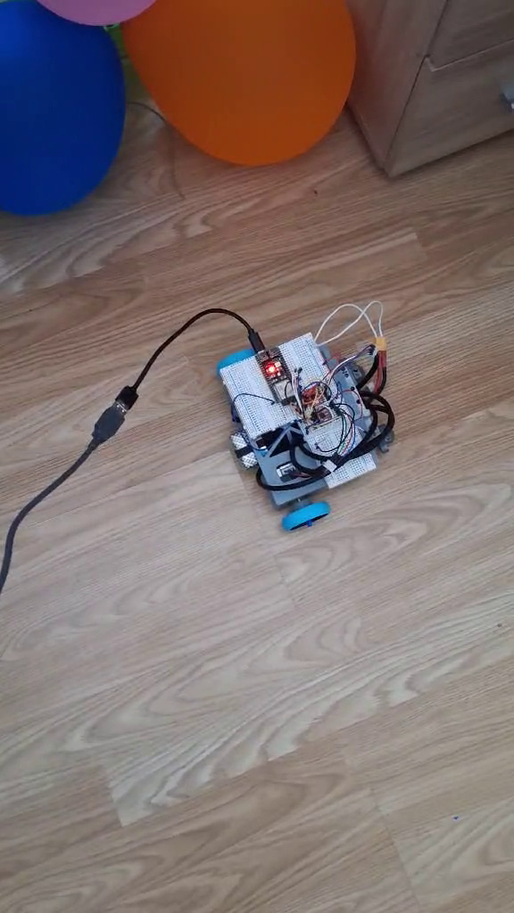 | 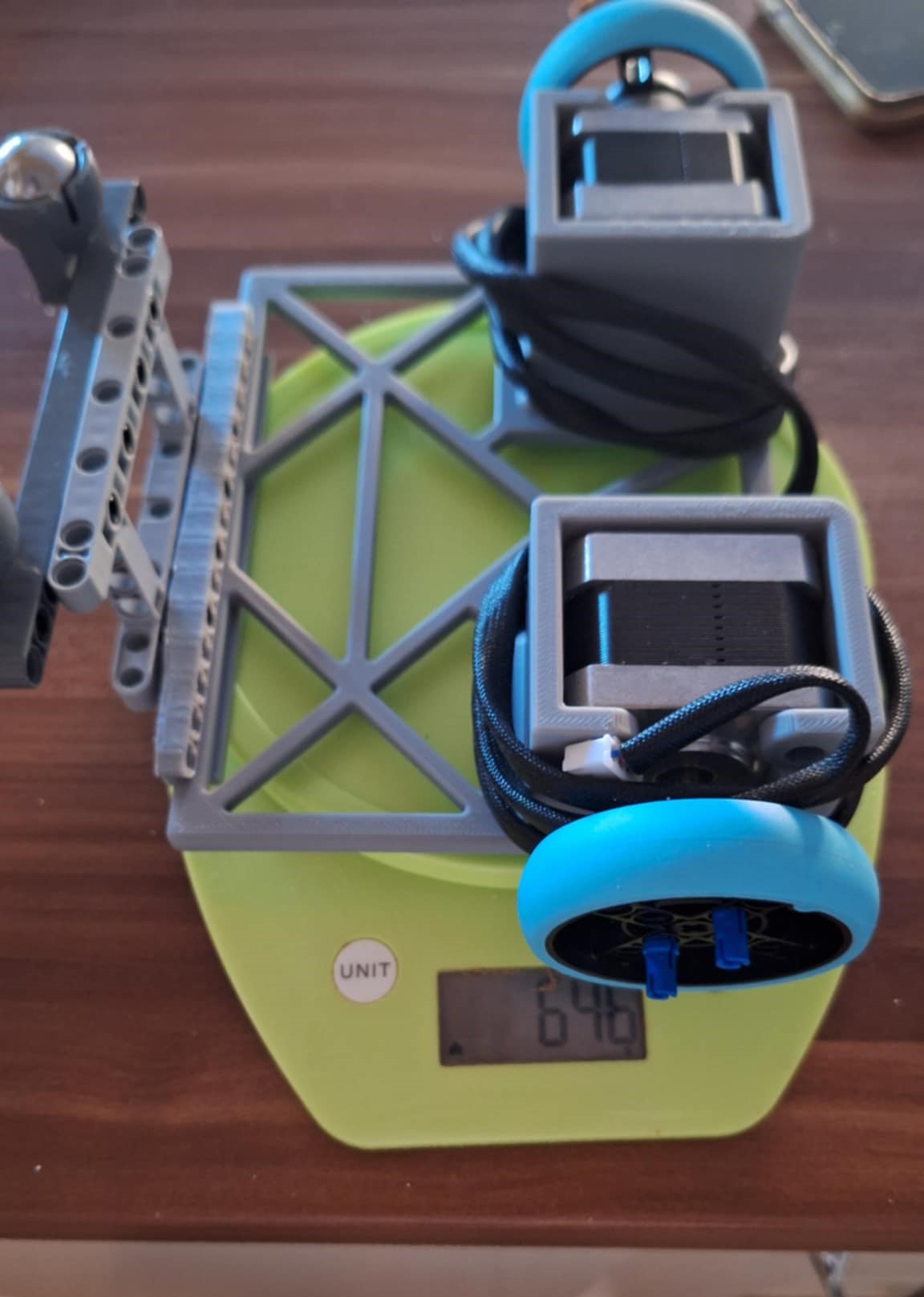 |
On the left, the design process (click for video!), and on the right, the finished, printed components next to measurement instruments. The lattice structure provides optimal rigidity with minimal weight.
The robot's brain and nervous system are comprised of a custom Printed Circuit Board (PCB) designed by us, located in the Circuit/kicad/Robot fő nyák_v3/ folder. Our goal was to create a central board that integrates all control and sensor functions, minimizing wiring and maximizing reliability.
The main functional blocks of the PCB:
StealthChop2™ for silent operation and StallGuard2™ for sensorless homing.Battery-circuit.kicad_sch). The system monitors the battery status and provides protection against overcharging and deep discharge.ADS8688) is responsible for the precise digitization of analog sensor signals (e.g., distance sensors).
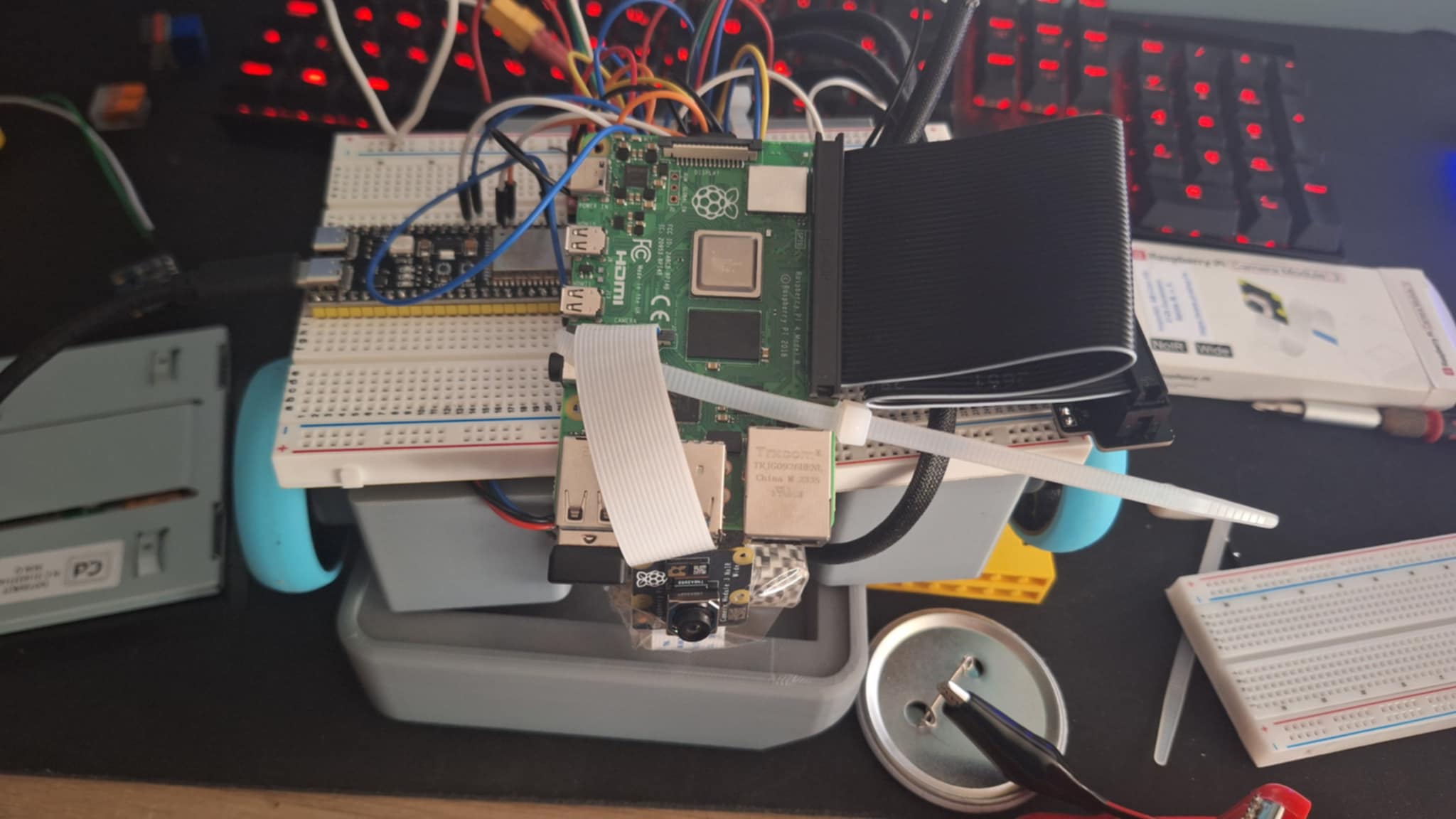
The "cable jungle"—an essential part of the prototyping phase, from which the final, clean PCB is born.
Hardware is only as good as the software that runs on it. The ProBot X1 is built on a sophisticated, two-tier software architecture.
The Python environment running on the Raspberry Pi is responsible for the robot's "intelligence."
Camera/ folder implements a complete image processing pipeline:
[Image blocked: Color Recognition in Action]
Click the image to watch the video! Based on the camera's image, the LED strip connected to the ESP32 lights up with the corresponding color.
The C++ firmware running on the ESP32 microcontroller, developed in the PlatformIO environment, ensures hard real-time operation.
robot modells/v1.0/Full_uart_communication_logic_v2/ project, has the structure: [START_BYTE, COMMAND_ID, PAYLOAD_LENGTH, PAYLOAD..., CHECKSUM]. This structure guarantees data integrity and robust operation.Meet the driving force behind JedlikBots, the students who power the project:
| Photo | Name | Role & Expertise |
|---|---|---|
 | Bence Nagy | Software Developer. Specializes in sensor data processing, embedded systems programming, and 3D modeling. Bence is responsible for the robot's hardware abstraction layer and the design of its mechanical components. |
 | Nándor Schmidt | Electronics Designer & Firmware Developer. The expert on the embedded systems behind the robots' "brains." He designs the PCBs and writes the low-level firmware, ensuring a perfect harmony between hardware and software. |
 | Bálint Buda | AI & Communications Developer. Bálint is responsible for implementing machine learning algorithms and for the robot's wired and wireless communication. |
We are proud of our achievements so far and have set even bigger goals for ourselves.
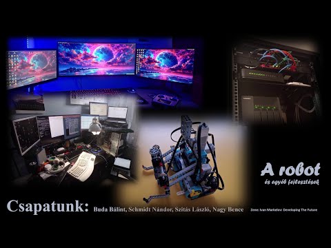
Click the image to watch our LEGO robot's competition run!
Developing the ProBot X1 and participating in international competitions require significant financial and technical resources. Our goal is to perform well at the WRO World Final, which requires building a world-class robot. This is where we need your help!
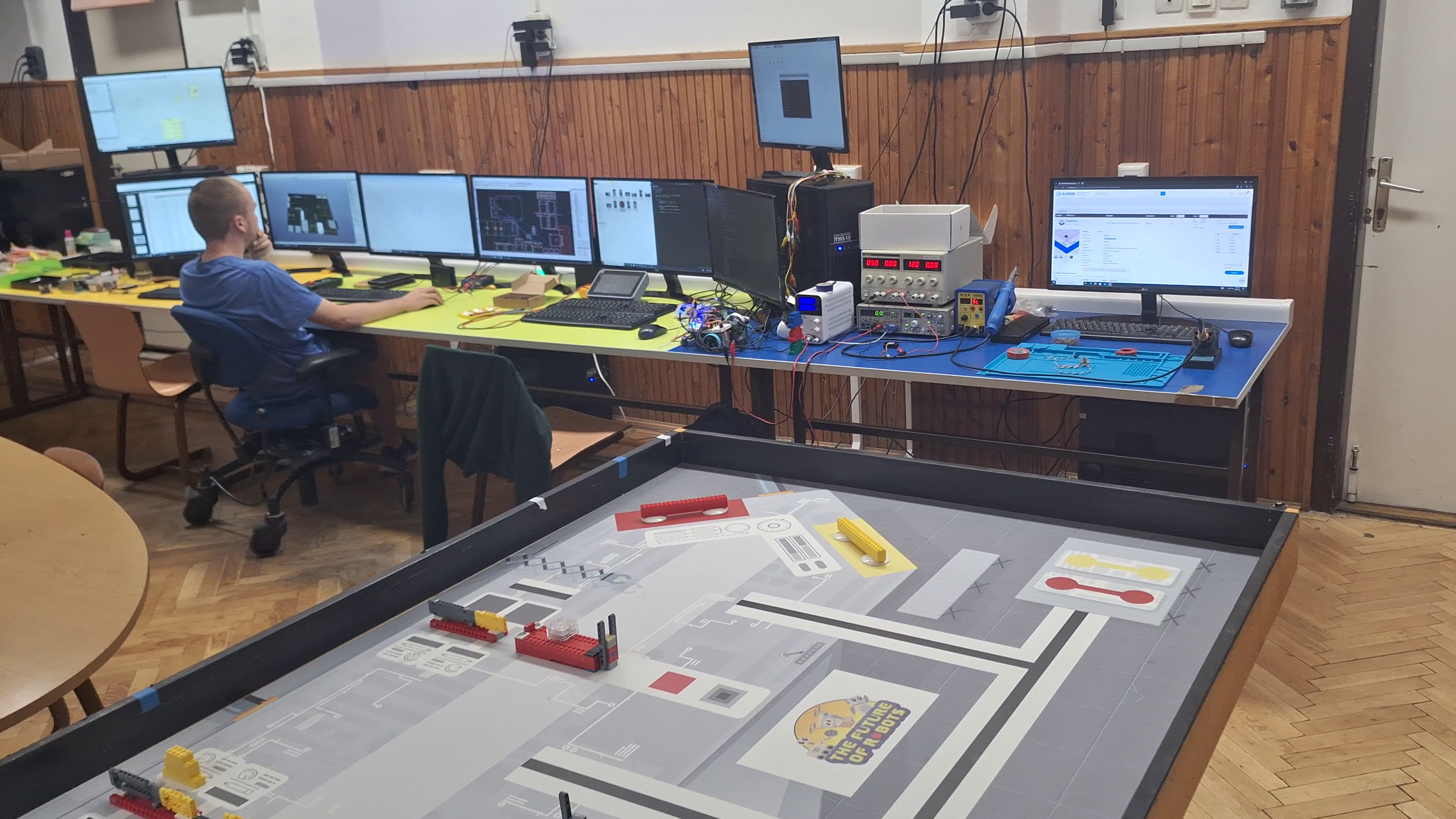
Click the image to see our workshop in action! This is where ideas and robots are born.
With Equipment: Modern components are essential for our project. Every single piece of donated equipment is a huge help. What we need most:
With Professional Mentorship: If you are an experienced engineer or developer and would like to share your knowledge, please contact us! A piece of good advice can be invaluable.
With Financial Support: Your financial contribution can directly support the purchase of components and our travel to competitions.
If you would like to contribute to our success, please write to us!
We are deeply grateful to our current sponsors who believe in us and support our work!


This repository documents the entire work of the JedlikBots team. You can find our projects in the following folders:
/Circuit/: Contains the designs for our custom Printed Circuit Boards (PCBs) in KiCad and Altium formats./Robot 3d/: 3D models of the robot's mechanical parts (STL, STP files)./robot modells/: Various software modules and experimental programs that implement the robot's functions (PlatformIO projects)./Camera/: Python scripts related to machine vision./media/: Images and videos of the robot, the team, and the competitions./web/: The source code for the team's official website.Thank you for your time! Follow our work and cheer for us at the next competition!
Üdvözlünk a JedlikBots hivatalos GitHub oldalán! 🎓🤖 Mi vagyunk a Győri Jedlik Ányos Technikum szoftverfejlesztő és robotika iránt elkötelezett diákcsapata. Szenvedélyünk a gépészet, az elektronika és a szoftverfejlesztés ötvözése, amellyel innovatív, valós problémákra választ adó robotikai megoldásokat hozunk létre. Célunk, hogy a megszerzett tudást hazai és nemzetközi versenyeken kamatoztassuk, és inspiráljuk a jövő mérnökgenerációját.
A ProBot X1 a csapatunk zászlóshajója: egy professzionális, moduláris robotplatform, amelyet kifejezetten a WRO (World Robot Olympiad) nemzetközi versenysorozatra, valamint más magas szintű technológiai kihívásokra terveztünk. A robot fejlesztése során a legmodernebb technológiákat alkalmazzuk, hogy egy valóban versenyképes és sokoldalú eszközt hozzunk létre.
A ProBot X1 korai, de működő prototípusa a fejlesztői környezetben.
A ProBot X1 nem csupán egy robot – egy komplex, precíziós mérnöki munkával megtervezett és épített rendszer. Az alábbiakban részletesen bemutatjuk a projekt műszaki hátterét.
A robot fizikai váza és minden mechanikai eleme teljes mértékben egyedi tervezésű. A tervezési filozófiánk középpontjában a modularitás, a robusztusság és a gyors iterálhatóság áll.
| Tervezés a CAD Szoftverben (Videó) | A Kész, Nyomtatott Alkatrészek |
|---|---|
| |
Bal oldalon a tervezési folyamat (kattints a videóért!), jobb oldalon a kész, nyomtatott alkatrészek a mérőműszerek mellett. A rácsszerkezet optimális merevséget biztosít minimális súly mellett.
A robot agyát és idegrendszerét egy általunk, a Circuit/kicad/Robot fő nyák_v3/ mappában tervezett egyedi nyomtatott áramkör (PCB) alkotja. A célunk egy olyan központi panel létrehozása volt, amely integrálja az összes vezérlési és szenzorikai funkciót, minimalizálva a kábelezést és maximalizálva a megbízhatóságot.
A NyÁK fő funkcionális blokkjai:
StealthChop2™ a hangtalan működésért és a StallGuard2™ a szenzor nélküli végállás-érzékelésért.Battery-circuit.kicad_sch). A rendszer figyeli az akkumulátor állapotát, és védelmet nyújt a túltöltés és mélykisülés ellen.ADS8688) felel az analóg szenzorok (pl. távolságmérők) jeleinek precíz digitalizálásáért.
A "kábel dzsungel" – a prototípus fázis elengedhetetlen része, amelyből a végleges, letisztult PCB megszületik.
A hardver csak annyit ér, amennyit a szoftver kihoz belőle. A ProBot X1 egy kifinomult, kétlépcsős szoftveres architektúrára épül.
A Raspberry Pi-on futó Python környezet felel a robot "intelligenciájáért".
Camera/ mappában található kódjaink egy komplett képfeldolgozási folyamatot valósítanak meg:
[Image blocked: Színfelismerés Működés Közben]
Kattints a képre a videó megtekintéséhez! A kamera képe alapján az ESP32-re kötött LED-szalag a megfelelő színnel világít.
Az ESP32 mikrokontrolleren futó, PlatformIO környezetben fejlesztett C++ firmware biztosítja a kőkemény valós idejű működést.
robot modells/v1.0/Full_uart_communication_logic_v2/ projektünkben kidolgozott protokoll felépítése: [START_BYTE, PARANCS_ID, ADAT_HOSSZ, ADATOK..., ELLENŐRZŐ_ÖSSZEG]. Ez a struktúra garantálja az adatok sértetlenségét és a robusztus működést.Ismerd meg a JedlikBots motorjait, a diákokat, akik a projekt mögött állnak:
| Fotó | Név | Szerepkör és szakterület |
|---|---|---|
| Nagy Bence | Szoftverfejlesztő. Specializációja a szenzoradatok feldolgozása, a beágyazott rendszerek programozása és a 3D modellezés. Bence felelős a robot hardverközeli szoftverrétegéért és a mechanikai elemek tervezéséért. |
| Schmidt Nándor | Elektronikai Tervező & Firmware Fejlesztő. A robot "agya" mögött álló beágyazott rendszerek szakértője. Ő tervezi a PCB-ket és írja az alacsony szintű firmware-t, biztosítva a hardver és szoftver tökéletes összhangját. |
| Buda Bálint | AI & Kommunikációs Fejlesztő. Bálint felelős a gépi tanulási algoritmusok implementálásáért és a robotok vezetékes és vezeték nélküli kommunikációjáért. |
Büszkék vagyunk az eddig elért sikereinkre, és még nagyobb célokat tűztünk ki magunk elé.
Kattints a képre a LEGO robotunk versenyfutamának megtekintéséhez!
A ProBot X1 fejlesztése és a nemzetközi versenyeken való részvétel komoly anyagi és technikai erőforrásokat igényel. Célunk a WRO világdöntőn való eredményes szereplés, amihez egy világszínvonalú robot megépítése szükséges. Itt kérjük a te segítségedet!
Kattints a képre, és nézd meg a műhelyünket működés közben! Itt születnek az ötletek és a robotok.
Eszközökkel: A projektünkhöz elengedhetetlenek a modern alkatrészek. Minden egyes felajánlott eszköz óriási segítséget jelent. Amire a legnagyobb szükségünk van:
Szakmai Mentorálással: Ha tapasztalt mérnök, fejlesztő vagy, és szívesen megosztanád a tudásod, vedd fel velünk a kapcsolatot! Egy-egy jó tanács aranyat érhet.
Anyagi Támogatással: Pénzügyi hozzájárulásoddal közvetlenül támogathatod az alkatrészek beszerzését és a versenyekre való utazásunkat.
Ha szeretnél hozzájárulni a sikereinkhez, írj nekünk!
Hálásan köszönjük eddigi támogatóinknak, akik hisznek bennünk és segítik a munkánkat!
Ez a repository a JedlikBots csapat teljes munkáját dokumentálja. Az alábbi mappákban találod a projektjeinket:
/Circuit/: A robotunkhoz tervezett egyedi nyomtatott áramkörök (PCB) tervei KiCad és Altium formátumban./Robot 3d/: A robot mechanikai alkatrészeinek 3D modelljei (STL, STP fájlok)./robot modells/: Különböző szoftveres modulok és kísérleti programok, amelyek a robot funkcióit valósítják meg (PlatformIO projektek)./Camera/: A gépi látással kapcsolatos Python scriptek./media/: Képek és videók a robotról, a csapatról és a versenyekről./web/: A csapat hivatalos weboldalának forráskódja.Köszönjük, hogy időt szántál ránk! Kövesd a munkánkat, és szurkolj nekünk a következő versenyen!
| Qty | Value | Footprint | References |
|---|---|---|---|
| 74 | 1uf | Capacitor_SMD:C_0805_2012Metric | C10, C100, C101, C103, C104, C105, C106, C107, C110, C111, C116, C117, C118, C119, C121, C124 +58 |
| 41 | 2.2K 1% | Resistor_SMD:R_0805_2012Metric | R121, R122, R123, R124, R125, R126, R127, R128, R129, R130, R131, R132, R133, R134, R135, R136 +25 |
| 22 | IRLML2502 | Package_TO_SOT_SMD:SOT-23 | Q10, Q11, Q12, Q13, Q14, Q15, Q16, Q17, Q18, Q19, Q20, Q21, Q22, Q23, Q24, Q25 +6 |
| 18 | Conn_01x04_Pin | Connector_JST:JST_PH_B4B-PH-K_1x04_P2.00mm_Vertical | I2C_0x70_1, I2C_0x70_2, I2C_0x70_3, I2C_0x70_4, I2C_0x70_5, I2C_0x70_6, I2C_0x70_7, I2C_0x70_8, I2C_0x71_1, I2C_0x71_2, I2C_0x71_3, I2C_0x71_4, I2C_0x71_5, I2C_0x71_7, I2C_0x71_8, I2C_1 +2 |
| 16 | 0.025Ω | Resistor_SMD:R_1206_3216Metric | R33, R34, R35, R36, R37, R38, R39, R40, R41, R42, R43, R44, R45, R46, R47, R48 |
| 16 | INA226 | Package_SO:VSSOP-10_3x3mm_P0.5mm | U15, U16, U17, U18, U19, U20, U21, U22, U23, U24, U25, U26, U27, U28, U29, U30 |
| 14 | 100k | Resistor_SMD:R_0805_2012Metric | R76, R77, R78, R79, R80, R81, R82, R83, R98, R99, R100, R101, R102, R103 |
| 14 | 100n | Capacitor_SMD:C_0805_2012Metric | C5, C6, C7, C11, C41, C42, C43, C44, C45, C46, C64, C65, C66, C67 |
| 14 | TestPoint | TestPoint:TestPoint_Pad_D2.0mm | TP1, TP2, TP3, TP4, TP7, TP8, TP9, TP10, TP11, TP12, TP13, TP14, TP15, TP16 |
| 13 | 10k | Resistor_SMD:R_0805_2012Metric | R18, R72, R73, R74, R75, R84, R85, R88, R89, R90, R91, R94, R95 |
| 11 | 470uf | Capacitor_SMD:CP_Elec_8x10 | C56, C57, C58, C74, C75, C97, C102, C139, C140, C142, C143 |
| 10 | nf | Capacitor_SMD:C_0805_2012Metric | C47, C48, C49, C53, C54, C55, C68, C69, C72, C73 |
| 8 | LED | Diode_SMD:D_1206_3216Metric | D4, D5, D6, D7, D8, D9, D10, D11 |
| 7 | 10uf | Capacitor_Tantalum_SMD:CP_EIA-3528-21_Kemet-B | C131, CT4, CT5, CT6, CT7, CT8, CT9 |
| 7 | 15K 1% | Resistor_SMD:R_0805_2012Metric | R1, R26, R56, R58, R60, R66, R68 |
| 6 | 100uf | Capacitor_Tantalum_SMD:CP_EIA-7343-31_Kemet-D | C78, C129, C130, CT1, CT2, CT3 |
| 6 | 12K 1% | Resistor_SMD:R_0805_2012Metric | R22, R52, R53, R54, R63, R64 |
| 6 | 1k | Resistor_SMD:R_0805_2012Metric | R8, R9, R15, R69, R70, R71 |
| 6 | 5.1K 1% | Resistor_SMD:R_0805_2012Metric | R23, R24, R29, R30, R31, R32 |
| 6 | Conn_01x02_Socket | Connector_JST:JST_PH_B2B-PH-K_1x02_P2.00mm_Vertical | DC1, DC2, DC3, DC4, DC5, DC6 |
| 5 | 1.2nF | Capacitor_SMD:C_0805_2012Metric | C50, C51, C52, C70, C71 |
| 5 | 10K | Resistor_SMD:R_0805_2012Metric | R115, R116, R117, R118, R119 |
| 5 | 10R | Resistor_SMD:R_0805_2012Metric | R49, R50, R51, R61, R62 |
| 5 | 47K 1% | Resistor_SMD:R_0805_2012Metric | R55, R57, R59, R65, R67 |
| 5 | AP64501SP-13 | Package_SO:SOIC-8-1EP_3.9x4.9mm_P1.27mm_EP2.95x4.9mm_Mask2.71x3.4mm_ThermalVias | U31, U32, U33, U34, U35 |
| 5 | SRN6045TA-3R3Y | Inductor_SMD:L_Bourns_SRN6045TA | L1, L2, L3, L4, L5 |
| 5 | TPD4EUSB30 | Package_SON:USON-10_2.5x1.0mm_P0.5mm | U4, U5, U10, U12, U14 |
| 5 | TS5A23157DGSR | CM5IO:SOP50P490X110-10N | U59, U60, U61, U62, U66 |
| 4 | 10u | Capacitor_Tantalum_SMD:CP_EIA-3528-21_Kemet-B | C1, C3, C4, C15 |
| 4 | 320 | Resistor_SMD:R_0805_2012Metric | R86, R87, R92, R93 |
| 4 | 36K 1% | Resistor_SMD:R_0805_2012Metric | R19, R20, R21, R25 |
| 4 | Conn_01x03_Socket | Connector_JST:JST_PH_B3B-PH-K_1x03_P2.00mm_Vertical | SERVO1, SERVO2, SERVO3, SERVO4 |
| 4 | Conn_01x06_Socket | Connector_JST:JST_PH_B6B-PH-K_1x06_P2.00mm_Vertical | SPI1, SPI2, SPI3, SPI4 |
| 4 | Stepper_Motor_unipolar_6pin | Connector_JST:JST_PH_B6B-PH-K_1x06_P2.00mm_Vertical | M4, M5, M6, M7 |
| 4 | TMC2240_SILENTSTEPSTICK | CM5IO:TMC2209 | U48, U49, U50, U51 |
| 3 | 0.022-μF | Capacitor_SMD:C_0805_2012Metric | C123, C126, C137 |
| 3 | 100nf | Capacitor_SMD:C_0805_2012Metric | C13, C79, C84 |
| 3 | 4.7k | Resistor_SMD:R_0805_2012Metric | R5, R6, R7 |
| 3 | 470uf | Capacitor_SMD:C_0805_2012Metric | C96, C98, C99 |
| 3 | 47k | Resistor_SMD:R_0805_2012Metric | R104, R105, R120 |
| 3 | AP22653W6 | Package_TO_SOT_SMD:SOT-23-6 | U1, U6, U9 |
| 3 | Conn_01x02_Pin | Connector_JST:JST_PH_B2B-PH-K_1x02_P2.00mm_Vertical | J31, J32, SPEAKER1 |
| 3 | SW_DIP_x08 | Button_Switch_SMD:SW_DIP_SPSTx08_Slide_Copal_CHS-08A_W5.08mm_P1.27mm_JPin | DSW1, DSW2, DSW3 |
| 3 | SW_Push | Connector_PinHeader_2.54mm:PinHeader_1x02_P2.54mm_Vertical | SW2, SW3, SW4 |
| 3 | USB_C_Receptacle_USB2.0_16P | Connector_USB:USB_C_Receptacle_Palconn_UTC16-G | J8, J9, J10 |
| 2 | 0.1uF | Capacitor_SMD:C_0805_2012Metric | C108, C109 |
| 2 | 1.5-kΩ | Resistor_SMD:R_0805_2012Metric | R106, R107 |
| 2 | 16 | Resistor_SMD:R_0805_2012Metric | R111, R112 |
| 2 | 22pF | Capacitor_SMD:C_0805_2012Metric | C112, C113 |
| 2 | 27pF | Capacitor_SMD:C_0805_2012Metric | C12, C14 |
| 2 | 330 | Resistor_SMD:R_0805_2012Metric | R113, R114 |
| 2 | 470R | Resistor_SMD:R_0805_2012Metric | R12, R13 |
| 2 | 690-019-298-412 | CM5IO:EDAC 690-019-298-412 | J3, J4 |
| 2 | C | Capacitor_SMD:C_0805_2012Metric | C120, C122 |
| 2 | Conn_01x22_Female | CM5IO:Hirose_FH12-22S-0.5SH_1x22-1MP_P0.50mm_Horizontal | DSI1, DSI2 |
| 2 | FSUSB42MUX | Package_SO:MSOP-10_3x3mm_P0.5mm | U8, U13 |
| 2 | FerriteBead | Resistor_SMD:R_2512_6332Metric | FB1, FB2 |
| 2 | IRLHM630PbF | Package_TO_SOT_SMD:PQFN_8x8 | Q1, Q26 |
| 2 | LED Green | Diode_SMD:D_1206_3216Metric | D1, D3 |
| 2 | MCP23S17_SO | Package_SO:SSOP-28_3.9x9.9mm_P0.635mm | U53, U54 |
| 2 | RT9742SNGV | Package_TO_SOT_SMD:TSOT-23 | U2, U36 |
| 2 | SS8050-G | Package_TO_SOT_SMD:SOT-23 | Q2, Q3 |
| 2 | TCA9548APWR | Package_SO:TSSOP-24_4.4x7.8mm_P0.65mm | U45, U46 |
| 2 | THD-02-R | Connector_PinHeader_2.54mm:PinHeader_2x02_P2.54mm_Vertical | J11, J13 |
| 2 | TestPoint | TestPoint:TestPoint_Pad_D4.0mm | TP5, TP6 |
| 1 | 0R | Resistor_SMD:R_0805_2012Metric | R10 |
| 1 | 100K 1% | Resistor_SMD:R_0805_2012Metric | R14 |
| 1 | 100uF | Capacitor_Tantalum_SMD:CP_EIA-7343-31_Kemet-D | C2 |
| 1 | 22 | Resistor_SMD:R_0805_2012Metric | R108 |
| 1 | 22Ω | Resistor_SMD:R_0805_2012Metric | R109 |
| 1 | 24MHz | Crystal:Crystal_SMD_HC49-SD | Y1 |
| 1 | 32.768MHz | Crystal:Crystal_SMD_HC49-SD | Y4 |
| 1 | 470uF | Capacitor_SMD:CP_Elec_8x10 | C16 |
| 1 | 5MHz | Crystal:Crystal_SMD_HC49-SD | Y3 |
| 1 | 690-008-221-904 | CM5IO:MOLEX_USB_67298-4090 | J7 |
| 1 | 74HC240 | Package_SO:TSSOP-20_4.4x6.5mm_P0.65mm | U47 |
| 1 | 74LVC1G07SE-7 | Package_TO_SOT_SMD:SOT-353_SC-70-5 | U3 |
| 1 | ADS8688 | Package_SO:TSSOP-38_4.4x9.7mm_P0.5mm | U63 |
| 1 | ASEK-32.768KHZ-L-R-T | Crystal:Crystal_SMD_3225-4Pin_3.2x2.5mm | U7 |
| 1 | BME280 | Package_LGA:Bosch_LGA-8_2.5x2.5mm_P0.65mm_ClockwisePinNumbering | U56 |
The 468 most common of 491 parts.
NBence0/JedlikBots
Welcome to the official GitHub page of JedlikBots! 🎓🤖 We are the dedicated team of software development and robotics students from the Jedlik Ányos Technical School in Győr, Hungary.

NBence0/JedlikBots
Welcome to the official GitHub page of JedlikBots! 🎓🤖 We are the dedicated team of software development and robotics students from the Jedlik Ányos Technical School in Győr, Hungary.

NBence0/JedlikBots
Welcome to the official GitHub page of JedlikBots! 🎓🤖 We are the dedicated team of software development and robotics students from the Jedlik Ányos Technical School in Győr, Hungary.

NBence0/JedlikBots
Welcome to the official GitHub page of JedlikBots! 🎓🤖 We are the dedicated team of software development and robotics students from the Jedlik Ányos Technical School in Győr, Hungary.

NBence0/JedlikBots
Welcome to the official GitHub page of JedlikBots! 🎓🤖 We are the dedicated team of software development and robotics students from the Jedlik Ányos Technical School in Győr, Hungary.

NBence0/JedlikBots
Welcome to the official GitHub page of JedlikBots! 🎓🤖 We are the dedicated team of software development and robotics students from the Jedlik Ányos Technical School in Győr, Hungary.

NBence0/JedlikBots
Welcome to the official GitHub page of JedlikBots! 🎓🤖 We are the dedicated team of software development and robotics students from the Jedlik Ányos Technical School in Győr, Hungary.

NBence0/JedlikBots
Welcome to the official GitHub page of JedlikBots! 🎓🤖 We are the dedicated team of software development and robotics students from the Jedlik Ányos Technical School in Győr, Hungary.

NBence0/JedlikBots
Welcome to the official GitHub page of JedlikBots! 🎓🤖 We are the dedicated team of software development and robotics students from the Jedlik Ányos Technical School in Győr, Hungary.

NBence0/JedlikBots
Welcome to the official GitHub page of JedlikBots! 🎓🤖 We are the dedicated team of software development and robotics students from the Jedlik Ányos Technical School in Győr, Hungary.


sanctuary-systems-com/rpi-cm5io-mini-itx
A mini ITX board with PCIe x16 based on the Raspberry Pi Comput Module 5 IO board

256foundation/libreboard
Open Source Bitcoin Mining Control Board

vega-d/CM4-nano-carrierboard
A simplified carrier board for RPI CM4 module featuring reduced footprint.
It measures 155 × 100 mm and has 6 copper layers, 1.6 mm thick.
491 parts, built around the 74HC240D, 74LVC1G07SE-7-MS, ADS8688IDB and BME280. The full list of its parts is on this page, with links to each part's symbol and footprint where PCBKit's library has them.
From the NBence0/JedlikBots repository on GitHub, at the commit this page was made from: the board is Circuit/kicad/Robot fő nyák_v3/CM5IO_második terv.kicad_pcb and its schematic Circuit/kicad/Adafruit-3.5in-TFT-Featherwing-PCB/Adafruit 3.5in 480x320 FeatherWing Rev B.kicad_sch. PCBKit opens the board in the browser, with nothing to install.
Its repository states no licence, so its author keeps all rights: ask NBence0 before reusing the design.