2 layers71.1 × 95.3 mm

 creyes2001/digital-clock
Bare-metal digital clock firmware for PIC18F4550 with multiplexed 7-segment display, EEPROM time storage, and cooperative scheduler.
Digital clock is an open-source printed circuit board by creyes2001, from the creyes2001/digital-clock repository on GitHub. It is a 2-layer board of 110.5 × 80 mm with 40 parts on 63 nets, routed with 416 tracks and 0 vias.
It is built around the PIC18F4550-I/PT and PN2222A. Its parts include 22 resistors, 5 ICs, 4 transistors, 4 switches and 2 connectors. It belongs with the lEDs and displays boards and the PIC boards of this library.


This is a bare-metal C project based on the Microchip PIC18F4550 microcontroller that implements a digital clock. The system uses multiplexed seven-segment displays to show the current time and provides a push-button interface for user configuration. The configured time is stored in the internal EEPROM memory.
The firmware is organized using a modular architecture that separates hardware drivers from application logic.
The modules include:
The system operates on a 1 ms system tick generated by the Timer2 peripherial. The tick drives a cooperative scheduler responsible for executing periodic tasks and maintaining the system time. The scheduler manages key tasks such as button input processing, display multiplexing, and timekeeping. This approach ensures accurate timing efficient CPU utilization.
My initial design used common-anode displays driven by PNP transistors through a Darlington array, chosen to limit the current going through the PIC's GPIO pins. This setup caused visible ghosting: the Darlington array's slow switching times and high saturation voltage drop meant that the previous digit didn't fully turn off before the next one turned on during multiplexing.
I redesigned the digit-drive stage with common-cathode displays driven directly by NPN transistors. The faster switching produced cleaner digit transitions and eliminated the ghosting entirely. This taught me that in embedded development, firmware correctness alone isn't enough — the underlying circuit topology can make or break a working system.
make all
make flash
make clean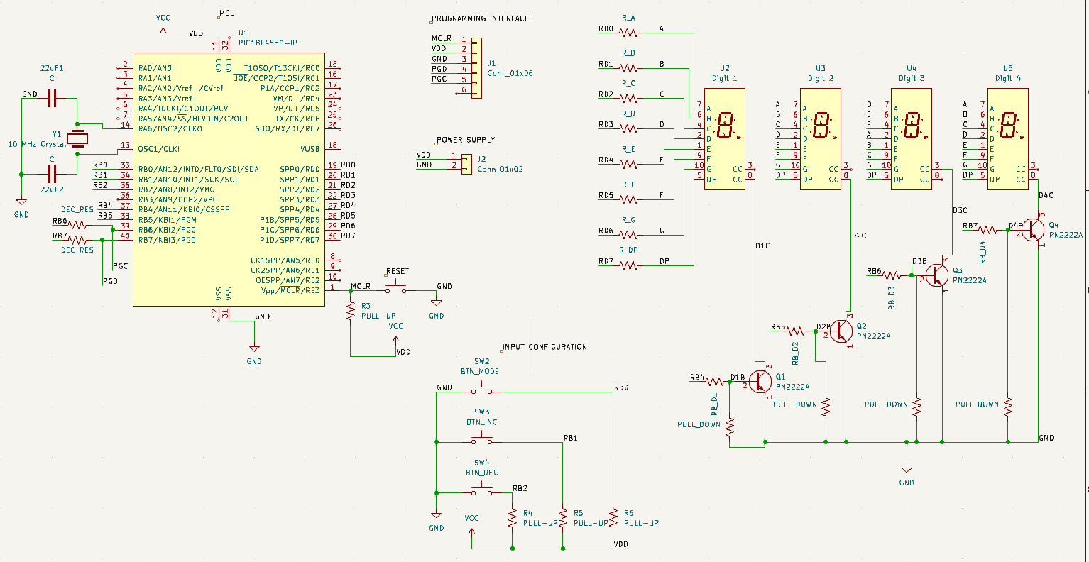
| Qty | Value | Footprint | References |
|---|---|---|---|
| 4 | PN2222A | Package_TO_SOT_THT:TO-92_Inline | Q1, Q2, Q3, Q4 |
| 4 | PULL-UP | Resistor_THT:R_Axial_DIN0207_L6.3mm_D2.5mm_P7.62mm_Horizontal | R3, R4, R5, R6 |
| 4 | PULL_DOWN | Resistor_THT:R_Axial_DIN0207_L6.3mm_D2.5mm_P7.62mm_Horizontal | R16, R18, R20, R22 |
| 2 | C | Capacitor_THT:C_Disc_D3.0mm_W1.6mm_P2.50mm | 22uF1, 22uF2 |
| 2 | DEC_RES | Resistor_THT:R_Axial_DIN0207_L6.3mm_D2.5mm_P7.62mm_Horizontal | R1, R2 |
| 1 | 16 MHz Crystal | Crystal:Crystal_HC49-4H_Vertical | Y1 |
| 1 | BTN_DEC | Button_Switch_THT:SW_PUSH_6mm | SW4 |
| 1 | BTN_INC | Button_Switch_THT:SW_PUSH_6mm | SW3 |
| 1 | BTN_MODE | Button_Switch_THT:SW_PUSH_6mm | SW2 |
| 1 | Conn_01x02 | Connector_Phoenix_MC_HighVoltage:PhoenixContact_MCV_1,5_2-G-5.08_1x02_P5.08mm_Vertical | J2 |
| 1 | Conn_01x06 | Connector_PinHeader_2.54mm:PinHeader_1x06_P2.54mm_Horizontal | J1 |
| 1 | Digit 1 | Display_7Segment:D1X8K | U2 |
| 1 | Digit 2 | Display_7Segment:D1X8K | U3 |
| 1 | Digit 3 | Display_7Segment:D1X8K | U4 |
| 1 | Digit 4 | Display_7Segment:D1X8K | U5 |
| 1 | PIC18F4550-IP | Package_DIP:DIP-40_W15.24mm | U1 |
| 1 | RB_D1 | Resistor_THT:R_Axial_DIN0207_L6.3mm_D2.5mm_P7.62mm_Horizontal | R15 |
| 1 | RB_D2 | Resistor_THT:R_Axial_DIN0207_L6.3mm_D2.5mm_P7.62mm_Horizontal | R17 |
| 1 | RB_D3 | Resistor_THT:R_Axial_DIN0207_L6.3mm_D2.5mm_P7.62mm_Horizontal | R19 |
| 1 | RB_D4 | Resistor_THT:R_Axial_DIN0207_L6.3mm_D2.5mm_P7.62mm_Horizontal | R21 |
| 1 | R_A | Resistor_THT:R_Axial_DIN0207_L6.3mm_D2.5mm_P7.62mm_Horizontal | R7 |
| 1 | R_B | Resistor_THT:R_Axial_DIN0207_L6.3mm_D2.5mm_P7.62mm_Horizontal | R8 |
| 1 | R_C | Resistor_THT:R_Axial_DIN0207_L6.3mm_D2.5mm_P7.62mm_Horizontal | R9 |
| 1 | R_D | Resistor_THT:R_Axial_DIN0207_L6.3mm_D2.5mm_P7.62mm_Horizontal | R10 |
| 1 | R_DP | Resistor_THT:R_Axial_DIN0207_L6.3mm_D2.5mm_P7.62mm_Horizontal | R14 |
| 1 | R_E | Resistor_THT:R_Axial_DIN0207_L6.3mm_D2.5mm_P7.62mm_Horizontal | R11 |
| 1 | R_F | Resistor_THT:R_Axial_DIN0207_L6.3mm_D2.5mm_P7.62mm_Horizontal | R12 |
| 1 | R_G | Resistor_THT:R_Axial_DIN0207_L6.3mm_D2.5mm_P7.62mm_Horizontal | R13 |
| 1 | SW_Push | Button_Switch_THT:SW_PUSH_6mm | SW1 |
It measures 110.5 × 80 mm and has 2 copper layers, 1.6 mm thick.
40 parts, built around the PIC18F4550-I/PT and PN2222A. The full list of its parts is on this page, with links to each part's symbol and footprint where PCBKit's library has them.
From the creyes2001/digital-clock repository on GitHub, at the commit this page was made from: the board is pcb/digital_clock/digital_clock.kicad_pcb and its schematic pcb/digital_clock/digital_clock.kicad_sch. PCBKit opens the board in the browser, with nothing to install.
Its repository states no licence, so its author keeps all rights: ask creyes2001 before reusing the design.


Carlos9852/Sistemas_Embarcados
Projeto I da disciplina de Sistema Embarcados e Microcontroladores


Esdras2/dspic30f-devboard-kit
Breadboard-friendly dsPIC30F4011 (DIP-40, all-THT) dev board—KiCad 8 hardware (Rev D) plus XC16 demo firmware, 12 V→5 V regulation, crystal clock & ICSP.


