4 layers73.7 × 80 mm

 cracked-machine/STM32MP1_TestBoard_RevB9
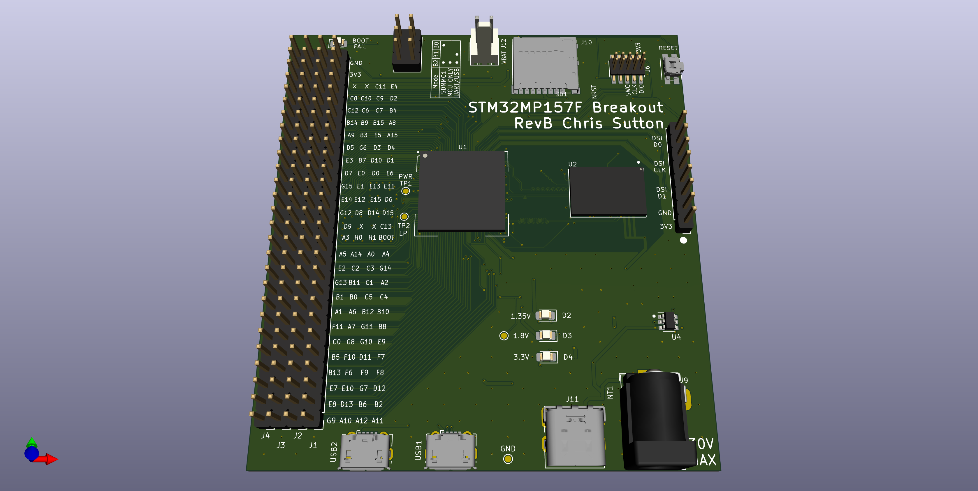
RevB breakout board for STM32MP1 (Dual A7 + M4). All pins routed to 0.1" headers.
STM32MP1 TestBoard RevB is an open-source printed circuit board by cracked-machine, from the cracked-machine/STM32MP1_TestBoard_RevB repository on GitHub, published under the MIT licence. It is a 4-layer board of 73.7 × 80 mm with 116 parts on 237 nets, routed with 24,729 tracks and 573 vias.
It is built around the TPS54202DDC, MT41K256M16TW-107:P and SE8233X2-HF, with the LQM18FN4R7M00D among its other parts. Its parts include 51 capacitors, 30 resistors, 13 connectors, 6 ICs and 4 diodes. It belongs with the microcontroller boards boards and the STM32 boards of this library.


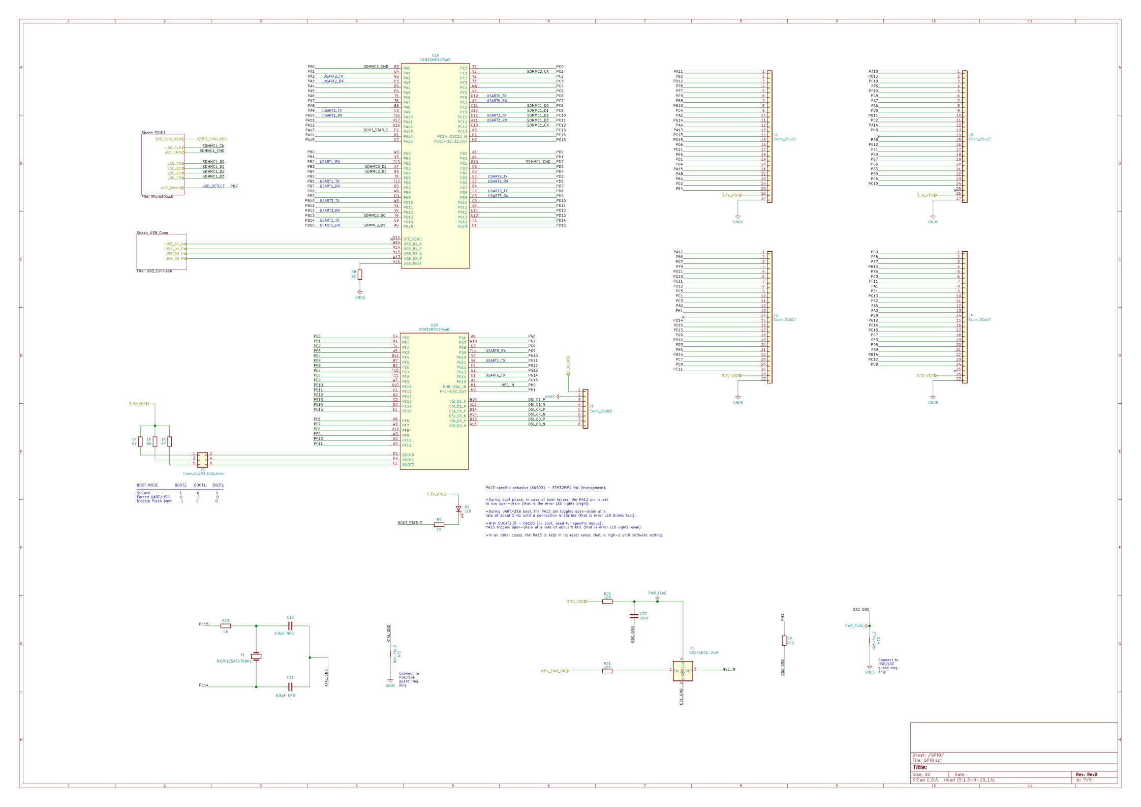
A development board for the STM32MP1 Application Microprocessor with all MPU pins routed through to 2.54mm headers. No exotic proprietary connectors needed!
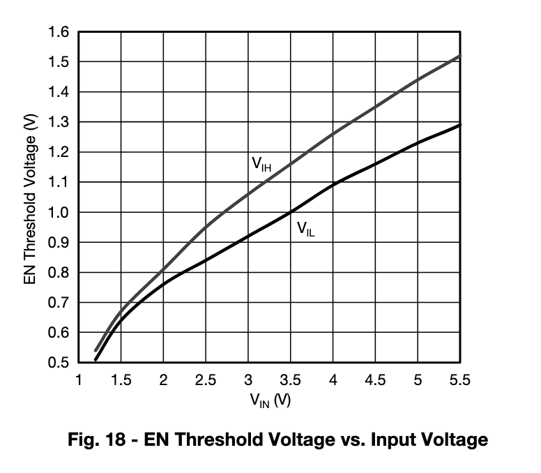
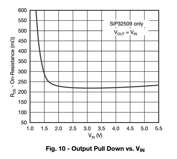
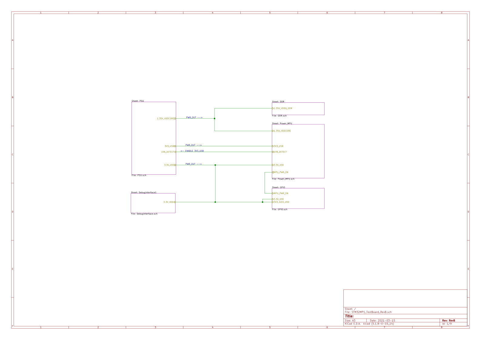
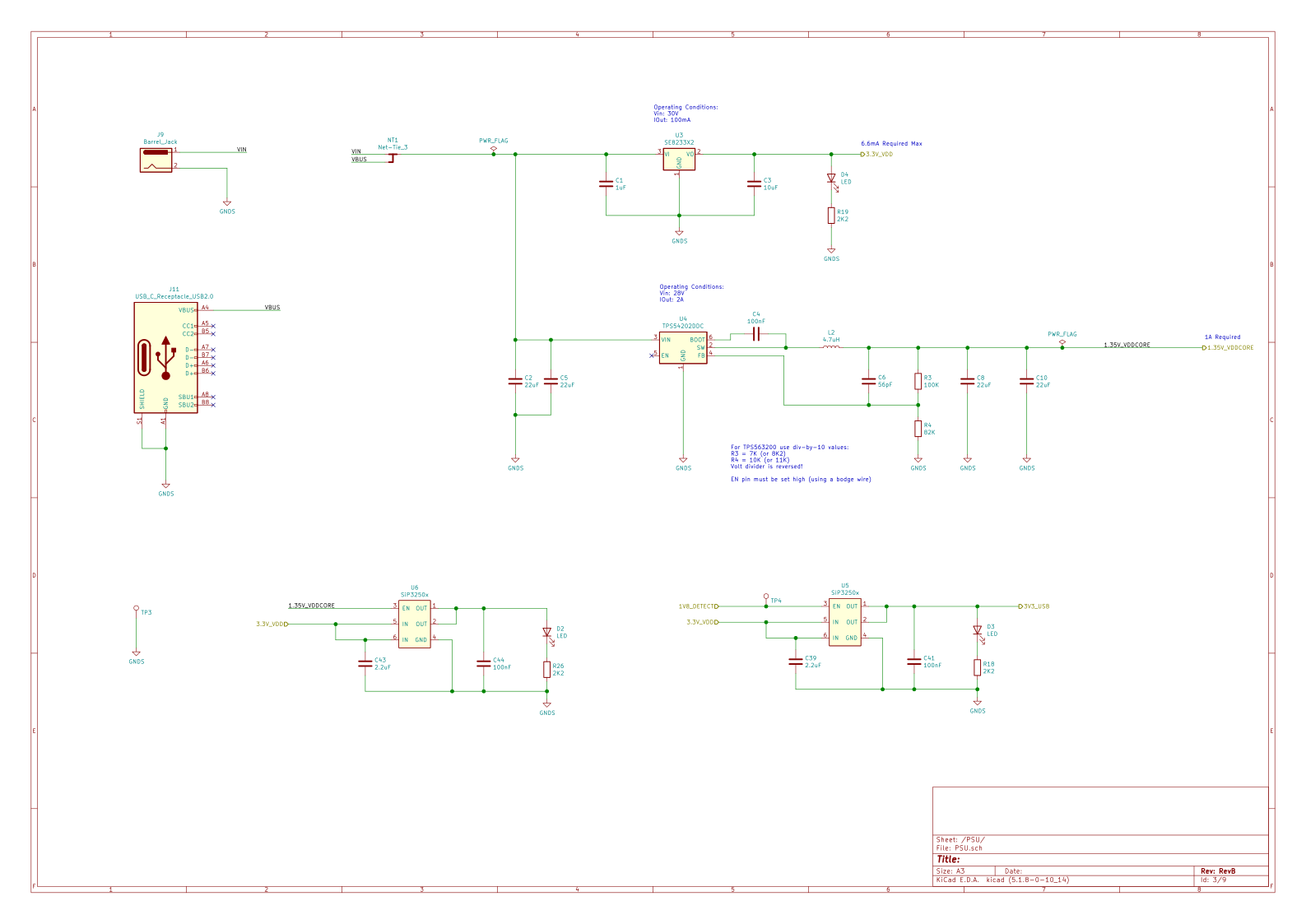
The power supply requirements for microprocessors are always complicated. I decided to use a discrete power supply scheme using a single LDO for the main 3.3V rail, a buck regulator for the DDR 1.35V rail and a load switch to detect the USB 1.8V rail. The latter comes from an internal regulator ands powers the VDD3V3_USBFS and VDD3V3_USBHS. This needs to be enabled only after the 1.8V rail comes up, so this needs to be enabled using a MOSFET. However, you need to pick a transistor that will fully switch on for 1.8V Vgs. After having some issues I played it safe with a load switch: the SIP3250, which turns on as low as 1.2V...according to the datasheet

The characteristics seem to back this up until you get to the Fig.10. Perhaps not quite as good as 1.2Vgs but even at 1.5Vgs, this is more than good enough for these requirements.
 |  |
|---|
Whether this is too much hassle when you can use a single PMIC is debatable. The sheer number of passive components needed to support a PMIC is eye-watering.
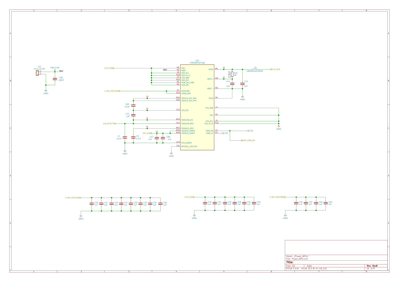
The table below lists the power supply scheme on this board:
| Power Supply Rail | MPU Pin Name | MPU Pin # | Comment |
|---|---|---|---|
| 3.3v | VDD VBAT VDD_PLL VDD_PLL2 VDD_ANA VDD_DSI PDR_ON_CORE PDR_ON | K6 H3 J5 G13 L3 A12 N1 N2 | Linear regulator (SE8233X2) |
| 3.3v | VDDA VREF+ | M4 N3 | via inductor L3 If JP4 is connected (default) |
| 3.3v | VDD3V3_USBFS VDD3V3_USBHS | W12 W15 | via NMOS (DMG2302U) when 1.85v rail is detected from MPU |
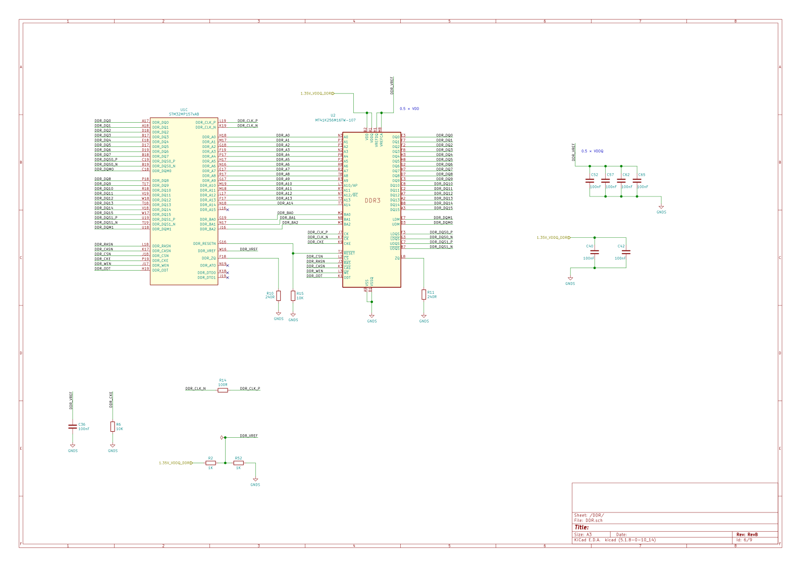
| 1.35v | VDD VDDQ VDDCORE VDDQ_DDR | B2 A1 E7 E15 | Buck regulator TPS54202 |
| 1.85v | VDDA1V8_REG | V11 | Internal regulator, externally connect to VDDA1V8_DSI (B12) |
| 1.2v | VDD1V2_DSI_REG | B16 | Internal regulator, externally connected to VDD1V2_DSI_PHY (A16) |
| 1.1v | VDDA1V1_REG | W11 | Interal regulator, internally connected. |
Note: 3.3v rail is also connected to:
| Overview | Power Supply |
|---|---|
 |  |
| STM32MP1 Power | STM32MP1 DDR |
|---|---|
 |  |
| STM32MP1 GPIO | STM32MP1 Debug |
|---|---|
 | 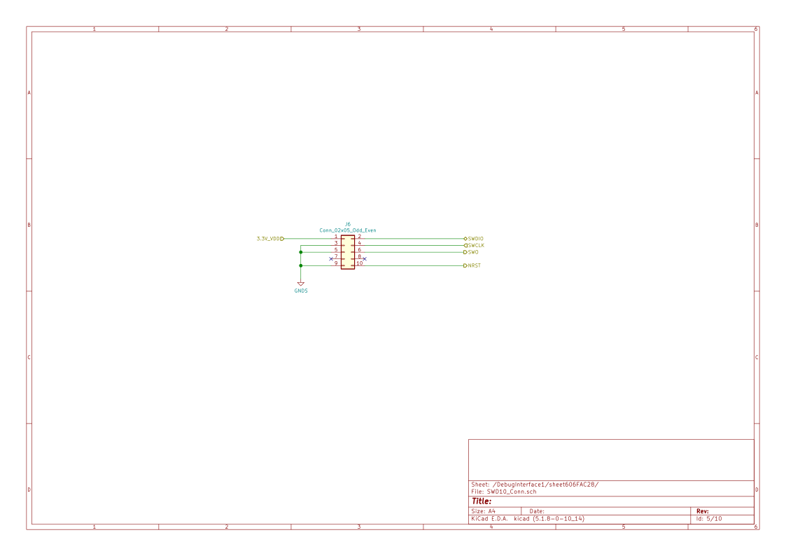 |
Before we boot the board with a Linux image. It is helpful to check the MPU is alive and responding. We can use the SEGGER JLink to connect to the cores via the SWD connector (J6).
BOOT pins must be set to B0 and B2.
JLinkExe -device STM32MP15XX_A7_0_DUALFLASH -if SWD -speed 4000 -autoconnect 1SEGGER J-Link Commander V6.98a (Compiled Mar 5 2021 17:04:44)
DLL version V6.98a, compiled Mar 5 2021 17:04:29
Connecting to J-Link via USB...O.K.
Firmware: J-Link V11 compiled Feb 4 2021 12:59:17
Hardware version: V11.00
S/N: 261002652
License(s): FlashBP, GDB
OEM: SEGGER-EDU
VTref=3.341V
Device "STM32MP15XX_A7_0_DUALFLASH" selected.
Connecting to target via SWD
ConfigTargetSettings() start
ConfigTargetSettings() end
InitTarget() start
InitTarget() end
Found SW-DP with ID 0x6BA02477
DPIDR: 0x6BA02477
AP map detection skipped. Manually configured AP map found.
AP[0]: AXI-AP (IDR: Not set)
AP[1]: APB-AP (IDR: Not set)
AP[2]: AHB-AP (IDR: Not set)BOOT pins must be set to B2 only.
JLinkExe -device STM32MP15XX_M4_DUALFLASH -if SWD -speed 4000 -autoconnect 1SEGGER J-Link Commander V6.98a (Compiled Mar 5 2021 17:04:44)
DLL version V6.98a, compiled Mar 5 2021 17:04:29
Connecting to J-Link via USB...O.K.
Firmware: J-Link V11 compiled Feb 4 2021 12:59:17
Hardware version: V11.00
S/N: 261002652
License(s): FlashBP, GDB
OEM: SEGGER-EDU
VTref=3.342V
Device "STM32MP15XX_M4_DUALFLASH" selected.
Connecting to target via SWD
ConfigTargetSettings() start
ConfigTargetSettings() end
InitTarget() start
InitTarget() end
Found SW-DP with ID 0x6BA02477
DPIDR: 0x6BA02477
AP map detection skipped. Manually configured AP map found.
AP[0]: AXI-AP (IDR: Not set)
AP[1]: APB-AP (IDR: Not set)
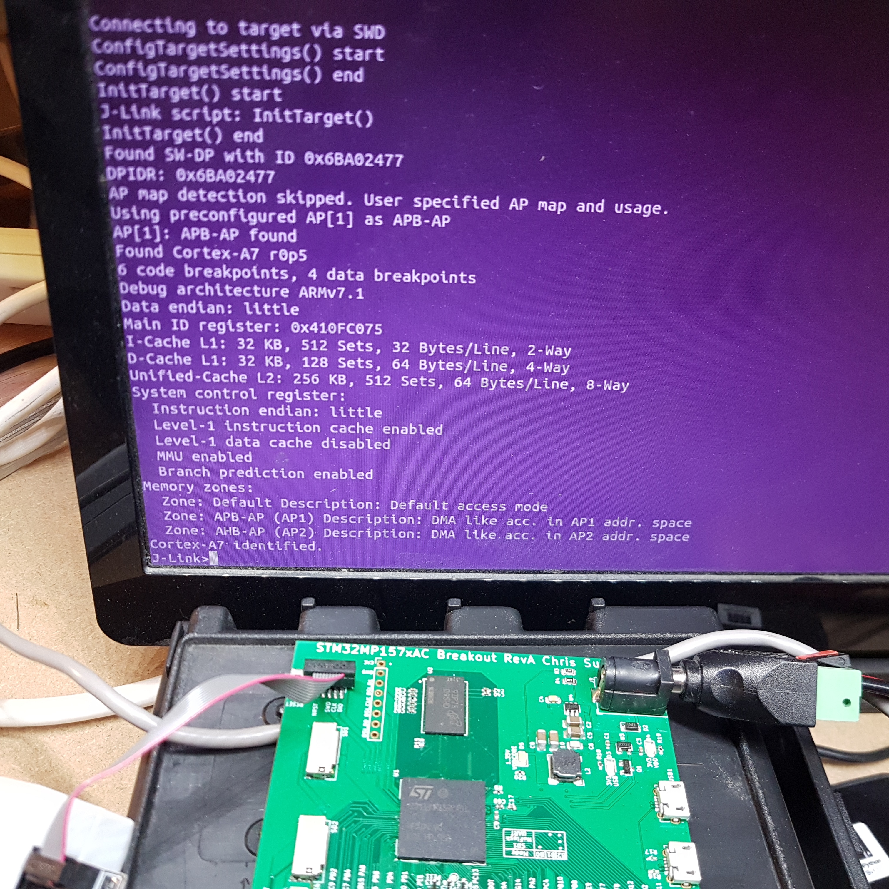
AP[2]: AHB-AP (IDR: Not set)Here is a photo successfully connecting to the A7 core on the assembled board using JLink (via SWD). It lives!
| Qty | Value | Footprint | References |
|---|---|---|---|
| 24 | 1uF | Capacitor_SMD:C_0402_1005Metric_Pad0.74x0.62mm_HandSolder | C1, C12, C14, C17, C18, C19, C20, C21, C22, C23, C24, C25, C26, C27, C28, C29 +8 |
| 11 | 100nF | Capacitor_SMD:C_0402_1005Metric_Pad0.74x0.62mm_HandSolder | C4, C36, C38, C40, C41, C42, C44, C52, C57, C62, C65 |
| 7 | 1K | Resistor_SMD:R_0402_1005Metric_Pad0.72x0.64mm_HandSolder | R1, R2, R5, R7, R9, R22, R52 |
| 5 | 47K | Resistor_SMD:R_0402_1005Metric_Pad0.72x0.64mm_HandSolder | R12, R13, R40, R41, R42 |
| 4 | 0R | Resistor_SMD:R_0402_1005Metric_Pad0.72x0.64mm_HandSolder | R16, R17, R23, R24 |
| 4 | 22uF | Capacitor_SMD:C_1206_3216Metric_Pad1.33x1.80mm_HandSolder | C2, C5, C8, C10 |
| 4 | Conn_01x27 | Connector_PinHeader_2.54mm:PinHeader_1x27_P2.54mm_Vertical | J1, J2, J3, J4 |
| 4 | LED | LED_SMD:LED_0805_2012Metric_Pad1.15x1.40mm_HandSolder | D1, D2, D3, D4 |
| 4 | TestPoint | TestPoint:TestPoint_Pad_D1.0mm | TP1, TP2, TP3, TP4 |
| 3 | 10K | Resistor_SMD:R_0402_1005Metric_Pad0.72x0.64mm_HandSolder | R6, R15, R21 |
| 3 | 10nF | Capacitor_SMD:C_0402_1005Metric_Pad0.74x0.62mm_HandSolder | C13, C15, C37 |
| 3 | 2.2uF | Capacitor_SMD:C_0402_1005Metric_Pad0.74x0.62mm_HandSolder | C7, C9, C69 |
| 3 | 2K2 | Resistor_SMD:R_0402_1005Metric_Pad0.72x0.64mm_HandSolder | R18, R19, R26 |
| 2 | 2.2uF | Capacitor_SMD:C_0603_1608Metric_Pad1.08x0.95mm_HandSolder | C39, C43 |
| 2 | 240R | Resistor_SMD:R_0402_1005Metric_Pad0.72x0.64mm_HandSolder | R10, R11 |
| 2 | 6.8pF NP0 | Capacitor_SMD:C_0402_1005Metric_Pad0.74x0.62mm_HandSolder | C11, C16 |
| 2 | Net-Tie_2 | TinyNetTies:NetTie-2_SMD_Pad0.127mm | NT2, NT3 |
| 2 | SiP3250x | Package_TO_SOT_SMD:SOT-23-6_Handsoldering | U5, U6 |
| 2 | USB_B_Micro | Connector_USB:USB_Micro-B_Molex-105017-0001 | J8, J14 |
| 1 | 0R | Capacitor_SMD:C_0402_1005Metric_Pad0.74x0.62mm_HandSolder | R25 |
| 1 | 100K | Resistor_SMD:R_0402_1005Metric_Pad0.72x0.64mm_HandSolder | R3 |
| 1 | 100R | Resistor_SMD:R_0402_1005Metric_Pad0.72x0.64mm_HandSolder | R14 |
| 1 | 10R | Resistor_SMD:R_0402_1005Metric_Pad0.72x0.64mm_HandSolder | R20 |
| 1 | 10uF | Capacitor_SMD:C_0402_1005Metric_Pad0.74x0.62mm_HandSolder | C3 |
| 1 | 3K | Resistor_SMD:R_0402_1005Metric_Pad0.72x0.64mm_HandSolder | R8 |
| 1 | 4.7uH | Inductor_SMD:L_Bourns-SRN6028 | L2 |
| 1 | 56pF | Capacitor_SMD:C_0402_1005Metric_Pad0.74x0.62mm_HandSolder | C6 |
| 1 | 82K | Resistor_SMD:R_0402_1005Metric_Pad0.72x0.64mm_HandSolder | R4 |
| 1 | Barrel_Jack | Connector_BarrelJack:BarrelJack_Horizontal | J9 |
| 1 | Conn_01x02 | Connector_Molex:Molex_KK-254_AE-6410-02A_1x02_P2.54mm_Vertical | J12 |
| 1 | Conn_01x08 | Connector_PinHeader_2.54mm:PinHeader_1x08_P2.54mm_Vertical | J7 |
| 1 | Conn_02x03_Odd_Even | Connector_PinHeader_2.54mm:PinHeader_2x03_P2.54mm_Vertical | J5 |
| 1 | Conn_02x05_Odd_Even | Connector_PinHeader_1.27mm:PinHeader_2x05_P1.27mm_Vertical_SMD | J6 |
| 1 | LQM18FN4R7M00D | Inductor_SMD:L_0201_0603Metric_Pad0.64x0.40mm_HandSolder | L3 |
| 1 | MT41K256M16TW-107 | Package_BGA:BGA-96_9.0x13.0mm_Layout2x3x16_P0.8mm | U2 |
| 1 | Micro_SD_Card_Det | Connector_Card:microSD_HC_Molex_104031-0811 | J10 |
| 1 | NX2012SA32768K1 | Crystal:Crystal_SMD_2012-2Pin_2.0x1.2mm_HandSoldering | Y1 |
| 1 | NX2016SA-24M | Oscillator:Oscillator_SMD_Abracon_ASE-4Pin_3.2x2.5mm | X1 |
| 1 | Net-Tie_3 | NetTie:NetTie-3_SMD_Pad0.5mm | NT1 |
| 1 | SE8233X2 | Package_TO_SOT_SMD:SOT-23 | U3 |
| 1 | STM32MP157xAB | STM32MP151_LFBGA:BGA-354_19x19_16.0x16.0mm | U1 |
| 1 | SW_SPST | Button_Switch_SMD:Panasonic_EVQPUK_EVQPUB | SW2 |
| 1 | TPS54202DDC | Package_TO_SOT_SMD:SOT-23-6 | U4 |
| 1 | USB_C_Receptacle_USB2.0 | MolexUSB_TypeC:213716-0001_THT_Socket_RightAngle | J11 |

cracked-machine/BassStationSequencerMidiController
Sequencer/MIDI Controller for Novation BassStation1

cracked-machine/STM32G031J6_Breakout
Breakout board for the 8 pin STM32 MCU. Onboard reset button and 30V input LDO.

ts-manuel/iMX6-Demo-Board
Demo board for the i.MX6ULL Single-Core Processor with Arm Cortex-A7 Core


SunnyYoshimitsu/CelestiCall
An attempt at making a somewhat modern smartphone with many functions.
It measures 73.7 × 80 mm and has 4 copper layers, 1.6 mm thick.
116 parts, built around the TPS54202DDC, MT41K256M16TW-107:P, SE8233X2-HF and LQM18FN4R7M00D. The full list of its parts is on this page, with links to each part's symbol and footprint where PCBKit's library has them.
From the cracked-machine/STM32MP1_TestBoard_RevB repository on GitHub, at the commit this page was made from: the board is STM32MP1_TestBoard_RevB/STM32MP1_TestBoard_RevB.kicad_pcb. PCBKit opens the board in the browser, with nothing to install.
Its repository publishes it under the MIT licence: you may reuse it on that licence's terms (keep the author's notice, and for a copyleft licence share your changes alike).