4 layers70.8 × 108 mm

 cr1tbit/ADCurrentDongle
Current measurement AND BNC connector breakout? Sign me the heck up!
ADCurrentDongle is an open-source printed circuit board by cr1tbit, from the cr1tbit/ADCurrentDongle repository on GitHub. It is a 4-layer board of 37 × 74 mm with 56 parts on 59 nets, routed with 484 tracks and 55 vias.
It is built around the MCP6004-E/P and 1N4148WT. Its parts include 20 resistors, 9 capacitors, 9 connectors, 5 diodes and 4 ICs.


Analog Discovery 2I actually use this simple board all the time, so decided to share it with the world.
It was made for these reasons:
There's an simple bulit-in comparator circuit that blinks a LED when the channel range is reached. The high-accuracy channel usually also blinks when the DUT performs some action, which is also an useful feedback I guess.
In Calib folder, there's an example digilent waveforms workspace that I use for current measurement (the software folder now has a standalone app that replaces it). Some things to note:
AD2 are noisy as hell when the current is under a couple of milliamps - hence the resistor in this area. Keep JP7 closed: without the pre-load, V+ delivers current in ~8 mA bursts at near-zero load (see M8 and M9 in the lab report).INA186s can be easilly callibrated out, using the provided script.Measurements, verification and known issues of this revision: ADCurrentDongle_LabSession (lab report).
What this device is NOT:
Stuff to improve:
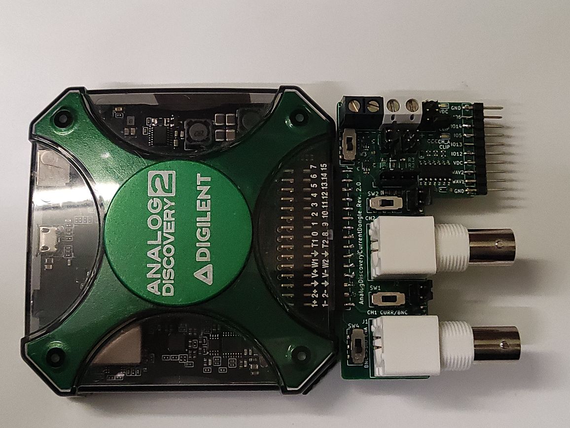
PCB connected to the Analog Discovery 2
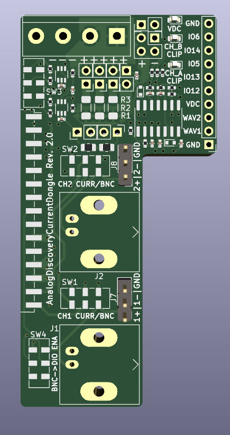
PCB render
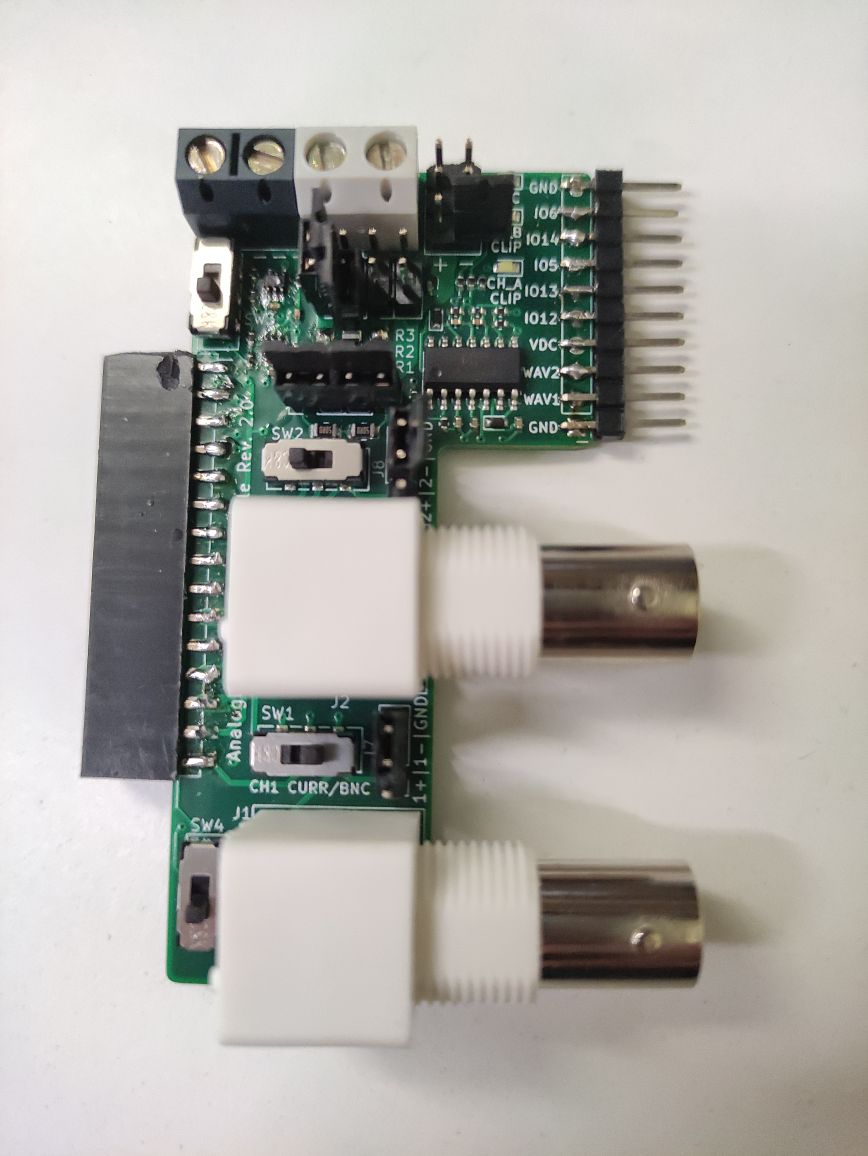
PCB IRL
| Qty | Value | Footprint | References |
|---|---|---|---|
| 6 | 3k3 | Resistor_SMD:R_0402_1005Metric | R7, R9, R10, R16, R17, R20 |
| 5 | 22n | Capacitor_SMD:C_0402_1005Metric | C2, C5, C6, C8, C9 |
| 5 | Jumper_2_Open | Connector_PinHeader_2.54mm:PinHeader_1x02_P2.54mm_Vertical | JP1, JP2, JP3, JP4, JP7 |
| 4 | 100n | Capacitor_SMD:C_0402_1005Metric | C1, C3, C4, C7 |
| 3 | 100k | Resistor_SMD:R_0402_1005Metric | R11, R14, R15 |
| 3 | LED | LED_SMD:LED_0603_1608Metric | D3, D4, D5 |
| 2 | 100 | Resistor_SMD:R_0402_1005Metric | R4, R5 |
| 2 | 1Meg | Resistor_SMD:R_0402_1005Metric | R12, R13 |
| 2 | 1N4148WT | Diode_SMD:D_SOD-523 | D1, D2 |
| 2 | 330 | Resistor_SMD:R_0402_1005Metric | R6, R8 |
| 2 | 50 | Resistor_SMD:R_0805_2012Metric | R18, R19 |
| 2 | CH1_DPDT | Button_Switch_SMD:SW_DPDT_CK_JS202011JCQN | SW1, SW4 |
| 2 | Conn_01x03 | Connector_PinHeader_2.54mm:PinHeader_1x03_P2.54mm_Vertical | J7, J8 |
| 2 | INA186AxDDxx | Package_TO_SOT_SMD:Texas_R-PDSO-G6 | U1, U2 |
| 1 | 0.2/0.1% | Resistor_SMD:R_1206_3216Metric_Pad1.30x1.75mm_HandSolder | R3 |
| 1 | 1/0.1% | Resistor_SMD:R_1206_3216Metric_Pad1.30x1.75mm_HandSolder | R2 |
| 1 | 5/0.1% | Resistor_SMD:R_1206_3216Metric_Pad1.30x1.75mm_HandSolder | R1 |
| 1 | AnalogDiscovery2 | critbit-transient-library:AnalogDiscovery2_side_con | U4 |
| 1 | BRD_EXT | Connector_PinSocket_2.54mm:PinSocket_2x02_P2.54mm_Vertical | J5 |
| 1 | CH2_DPDT | Button_Switch_SMD:SW_DPDT_CK_JS202011JCQN | SW2 |
| 1 | CURR_LP_SEL | Button_Switch_SMD:SW_DPDT_CK_JS202011JCQN | SW3 |
| 1 | Conn_01x02 | Connector_PinHeader_2.54mm:PinHeader_1x02_P2.54mm_Vertical | J4 |
| 1 | Conn_01x10 | Connector_PinHeader_2.54mm:PinHeader_1x10_P2.54mm_Vertical | J9 |
| 1 | EXT_SONDE1 | Connector_Coaxial:BNC_Amphenol_B6252HB-NPP3G-50_Horizontal | J1 |
| 1 | EXT_SONDE2 | Connector_Coaxial:BNC_Amphenol_B6252HB-NPP3G-50_Horizontal | J2 |
| 1 | MCP6004 | Package_SO:SOIC-14_3.9x8.7mm_P1.27mm | U3 |
| 1 | R_EXT | Connector_PinHeader_2.54mm:PinHeader_1x02_P2.54mm_Vertical | J6 |
| 1 | Screw_Terminal_01x04 | TerminalBlock:TerminalBlock_bornier-4_P5.08mm | J3 |

bkshepherd/DaisySeedProjects
A collection of hardware and software projects based around the Electro-Smith Daisy Seed

Neumi/open_echo
Open Source echo sounder / depth sounder / SONAR for bathymetry and research. Arduino based and compatible.

mobilinkd/NucleoTNC
The Nucleo TNC is a breadboard implementation of the Mobilinkd TNC3 using a STM32L432KC Nucleo32 board. This TNC faithfully implements the audio section and EEPROM storage of the TNC3.

westlicht/performer-hardware
PER|FORMER Eurorack Sequencer - Hardware Design Files

rusefi/hw_microRusEfi
microRusEfi board for rusEfi ECU

mck1117/wideband
The firmware/boards directory contains configuration for each board this firmware supports.

16n-faderbank/16nx
16nx is a controller for musical instruments. Sixteen faders,MIDI over USB and jack, CV out, and I2C out. Based around RP2040.
It measures 37 × 74 mm and has 4 copper layers, 4.69 mm thick.
56 parts, built around the MCP6004-E/P and 1N4148WT. The full list of its parts is on this page, with links to each part's symbol and footprint where PCBKit's library has them.
From the cr1tbit/ADCurrentDongle repository on GitHub, at the commit this page was made from: the board is ADCurrentDongle.kicad_pcb and its schematic ADCurrentDongle.kicad_sch. PCBKit opens the board in the browser, with nothing to install.
Its repository states no licence, so its author keeps all rights: ask cr1tbit before reusing the design.