2 layers142.1 × 106 mm

 computergeek1507/PB_1678
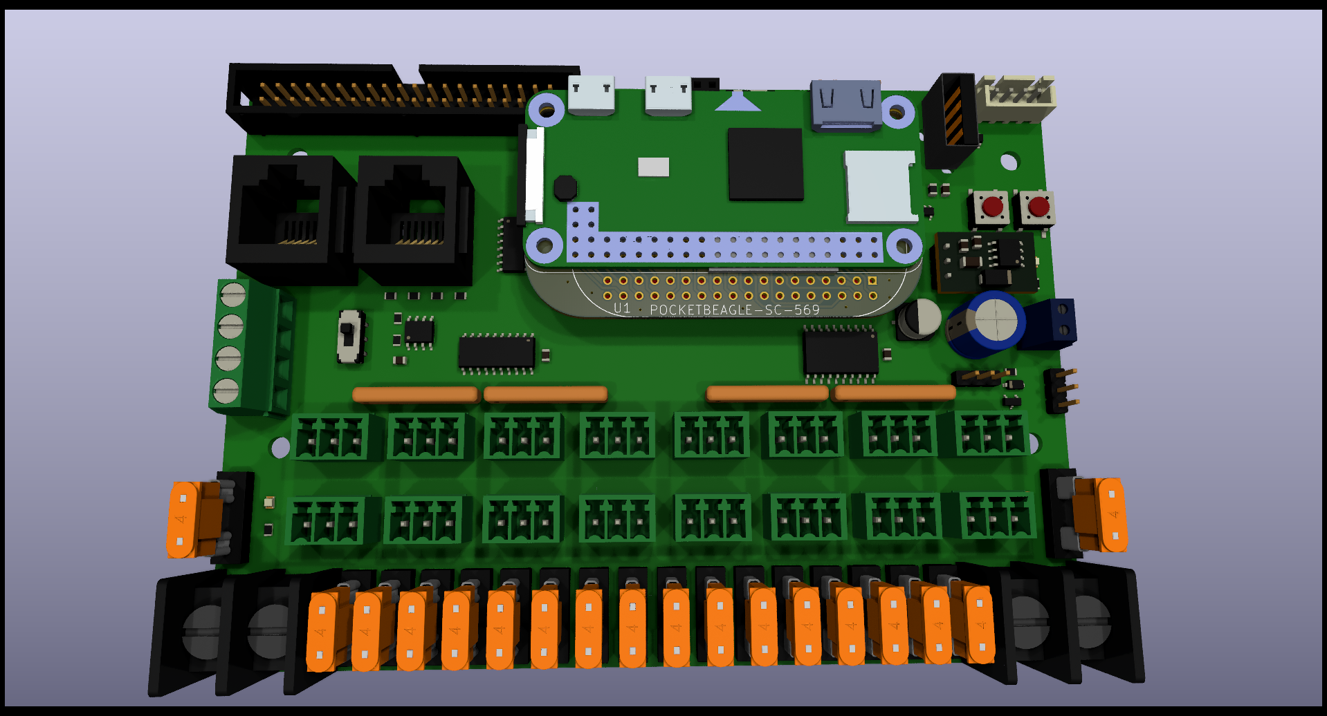
Open source FPP PB16 Pixel Controller
Receiver Out is an open-source printed circuit board by computergeek1507, from the computergeek1507/PB_16 repository on GitHub. It is a 2-layer board of 59.3 × 76.7 mm with 33 parts on 30 nets, routed with 180 tracks and 3 vias.
It is built around the 74HC125D, AM26C32IN and L7805, with the RJ45 and SB5100-T among its other parts. Its parts include 7 connectors, 4 capacitors, 4 fuses, 3 ICs and 3 diodes.


Copyright: Scott Hanson
This documentation describes Open Hardware and is licensed under the CERN OHL v. 1.2.
You may redistribute and modify this documentation under the terms of the CERN OHL v.1.2. (http://ohwr.org/cernohl). This documentation is distributed WITHOUT ANY EXPRESS OR IMPLIED WARRANTY, INCLUDING OF MERCHANTABILITY, SATISFACTORY QUALITY AND FITNESS FOR A PARTICULAR PURPOSE. Please see the CERN OHL v.1.2 for applicable conditions
This is an adapter to use a Raspberry Pi W with the PB16 Cape instead of a PocketBeagle. This only supports the 16 local ports and the serial ports. The Expansion header does not work. Open source applications were used to create this PCB. KiCad was used for the PCB design, and LibreOffice for the documentation.
To order your own PCB upload the gerber.zip file to your favorite PCB manufacture of choice, I personally use jlcpcb.com.
| Qty | Value | Footprint | References |
|---|---|---|---|
| 4 | 3544-2 | Scotts:FUSE_3544-2 | F1, F2, F3, F4 |
| 2 | 0.1uF | Capacitor_THT:C_Rect_L7.0mm_W2.0mm_P5.00mm | C3, C4 |
| 2 | 10uF | Capacitor_THT:CP_Radial_D5.0mm_P2.00mm | C1, C2 |
| 1 | 120 | Resistor_THT:R_Array_SIP8 | RN2 |
| 1 | 120 | Resistor_THT:R_Axial_DIN0207_L6.3mm_D2.5mm_P7.62mm_Horizontal | R2 |
| 1 | 1K | Resistor_THT:R_Axial_DIN0207_L6.3mm_D2.5mm_P7.62mm_Horizontal | R1 |
| 1 | 33 | Resistor_THT:R_Array_SIP8 | RN1 |
| 1 | 5V LED | LED_THT:LED_D3.0mm_Clear | D3 |
| 1 | 74HC125 | Package_DIP:DIP-14_W7.62mm_LongPads | U1 |
| 1 | AM26C32IN | Package_DIP:DIP-16_W7.62mm_LongPads | U3 |
| 1 | L7805 | Package_TO_SOT_THT:TO-220-3_Vertical | U2 |
| 1 | LOGO | Scotts:chewi_15 | G*** |
| 1 | Power In | Barrier_Blocks:BARRIER_BLOCK_1ROW_2POS | TB1 |
| 1 | Power In | TerminalBlock_MetzConnect:TerminalBlock_MetzConnect_Type701_RT11L02HGLU_1x02_P6.35mm_Horizontal | J5 |
| 1 | RJ45 | Connector_RJ:RJ45_Amphenol_54602-x08_Horizontal | J7 |
| 1 | SB5100-T | Diode_THT:D_DO-201AD_P12.70mm_Horizontal | D1 |
| 1 | String1 | Connector_Phoenix_MC:PhoenixContact_MCV_1,5_3-G-3.5_1x03_P3.50mm_Vertical | J1 |
| 1 | String2 | Connector_Phoenix_MC:PhoenixContact_MCV_1,5_3-G-3.5_1x03_P3.50mm_Vertical | J2 |
| 1 | String3 | Connector_Phoenix_MC:PhoenixContact_MCV_1,5_3-G-3.5_1x03_P3.50mm_Vertical | J3 |
| 1 | String4 | Connector_Phoenix_MC:PhoenixContact_MCV_1,5_3-G-3.5_1x03_P3.50mm_Vertical | J4 |
| 1 | VIN LED | LED_THT:LED_D3.0mm_Clear | D2 |
| 1 | VIN_Voltage | Connector_PinHeader_2.54mm:PinHeader_1x03_P2.54mm_Vertical | J6 |
The 27 most common of 33 parts.


MSTRocketDesignTeam/TestStand-Instrumentation-PCB
Rocket Team's Instrumentation Interface PCB


bot-hoven/bot-hoven-electrical
Electrical substem for Bot-Hoven. Includes KiCad files containing schematics and PCB designs for components in Bot-Hoven.


dennis9819/Z8C-Homebrew-Computer
To easily develop for my Z80 homebrew system, I designed a simple assempler development environment. This packs the following tasks into one script: zmac assembly object file creation (for xmodem upload) monitor file…

It measures 59.3 × 76.7 mm and has 2 copper layers, 1.6 mm thick.
33 parts, built around the 74HC125D, AM26C32IN, L7805 and RJ45. The full list of its parts is on this page, with links to each part's symbol and footprint where PCBKit's library has them.
From the computergeek1507/PB_16 repository on GitHub, at the commit this page was made from: the board is Receiver_Out/Receiver_Out.kicad_pcb. PCBKit opens the board in the browser, with nothing to install.
Its repository states no licence, so its author keeps all rights: ask computergeek1507 before reusing the design.