2 layers
Actuator Board V1
colin-skinner/Cesium
The main goal of this project is not simply to learn, but to focus on following through and finishing each sprint.
19 parts

 colin-skinner/Cesium
The main goal of this project is not simply to learn, but to focus on following through and finishing each sprint.
Flight Computer V1 is an open-source printed circuit board by colin-skinner, from the colin-skinner/Cesium repository on GitHub. It is a 2-layer board of 77.5 × 66 mm with 92 parts on 121 nets, routed with 669 tracks and 98 vias.
It is built around the ESP32-S3-WROOM-1U-N16, ICM-20948 and ADXL375BCCZ-RL7, with the AMS1117-1.8, USBLC6-2P6 and BLM21PG221SH1 among its other parts. Its parts include 27 capacitors, 21 resistors, 13 ICs, 9 diodes and 7 connectors. It belongs with the ESP32 boards of this library.


Library for all code related to development of my home server and space projects.
The main goal of this project is not simply to learn, but to focus on following through and finishing each sprint. Additionally, with working prototypes and code, I plan to use my designs to help aspiring engineers who want to develop these skills as well (open-source, potentially?).
Each stage will act as a sort of version that had a fully working system. When I add changes that completely break a system, then I'll re-rev the design for a new version.
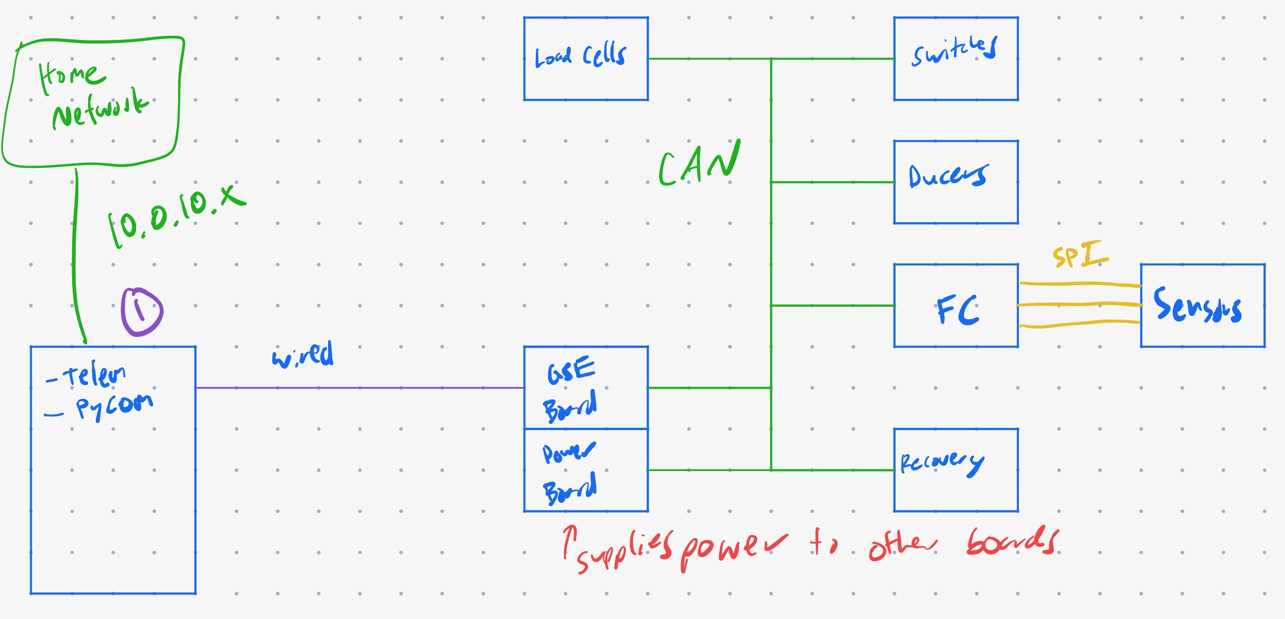
The goal of this design is to create an assortment of avionics boards useful for ground testing of amateur rocketry or satellites using the CAN bus and various ADCs for data collection.
ESP-32 Boards connected by CAN (for simplicity)
Boards designed to be small footprint and scaleable
EGSE Board connects to server via D+/D- USB OTG (ESP32 S3 capability)
Telemetry
List of Boards
GSE functionality (Python)
| Qty | Value | Footprint | References |
|---|---|---|---|
| 16 | 0.1uF | Capacitor_SMD:C_0603_1608Metric | C1, C2, C3, C4, C5, C6, C13, C15, C16, C17, C18, C21, C24, C25, C26, C27 |
| 6 | D | Diode_SMD:D_0603_1608Metric | D1, D2, D3, D4, D5, D6 |
| 5 | 10uF | Capacitor_SMD:C_0603_1608Metric | C7, C8, C9, C10, C11 |
| 5 | 1k | Resistor_SMD:R_0603_1608Metric | R4, R13, R16, R20, R21 |
| 3 | GREEN | LED_SMD:LED_0603_1608Metric_Pad1.05x0.95mm_HandSolder | D7, D8, D9 |
| 2 | 0 | Resistor_SMD:R_0603_1608Metric | R5, R6 |
| 2 | 12k | Resistor_SMD:R_0603_1608Metric | R7, R8 |
| 2 | 200m | Resistor_SMD:R_0603_1608Metric | R2, R3 |
| 2 | 22 | Resistor_SMD:R_0603_1608Metric | R14, R15 |
| 2 | 4.7k | Resistor_SMD:R_0603_1608Metric | R17, R18 |
| 2 | 5.1k | Resistor_SMD:R_0603_1608Metric | R9, R10 |
| 2 | Conn_01x06_Pin | Connector_PinSocket_2.54mm:PinSocket_1x06_P2.54mm_Vertical | J3, J7 |
| 2 | ICM-20948 | Sensor_Motion:InvenSense_QFN-24_3x3mm_P0.4mm | U4, U12 |
| 2 | INA233 | Package_SO:VSSOP-10_3x3mm_P0.5mm | U9, U10 |
| 2 | NPN | Package_TO_SOT_SMD:SOT-23 | Q1, Q2 |
| 1 | .1uF | Capacitor_SMD:C_0603_1608Metric | C19 |
| 1 | 120 | Resistor_SMD:R_0603_1608Metric | R1 |
| 1 | 1V8 | Connector_PinHeader_2.54mm:PinHeader_1x01_P2.54mm_Vertical | TP7 |
| 1 | 1uF | Capacitor_SMD:C_0603_1608Metric | C23 |
| 1 | 22.1k | Resistor_SMD:R_0603_1608Metric | R11 |
| 1 | 220 | Resistor_SMD:R_0603_1608Metric | R19 |
| 1 | 22u | Capacitor_SMD:C_0805_2012Metric_Pad1.18x1.45mm_HandSolder | C22 |
| 1 | 22uF | Capacitor_SMD:C_0603_1608Metric | C12 |
| 1 | 3V3 | Connector_PinHeader_2.54mm:PinHeader_1x01_P2.54mm_Vertical | TP5 |
| 1 | 4.7uF | Capacitor_SMD:C_0603_1608Metric | C20 |
| 1 | 47.5k | Resistor_SMD:R_0603_1608Metric | R12 |
| 1 | 47uF | Capacitor_SMD:C_0603_1608Metric | C14 |
| 1 | 5V | Connector_PinHeader_2.54mm:PinHeader_1x01_P2.54mm_Vertical | TP3 |
| 1 | 5V/3A | Fuse:Fuse_0603_1608Metric | F2 |
| 1 | ADXL375BCCZ-RL7 | Sensor_Motion:LGA_CC-14-1_ADI | U1 |
| 1 | AMS1117-1.8 | Package_TO_SOT_SMD:SOT-223-3_TabPin2 | U8 |
| 1 | BLM21PG221 | Inductor_SMD:L_0603_1608Metric_Pad1.05x0.95mm_HandSolder | FB1 |
| 1 | BOOT | Button_Switch_SMD:SW_SPST_B3S-1000 | SW2 |
| 1 | CP2102N-Axx-xQFN24 | Package_DFN_QFN:QFN-24-1EP_4x4mm_P0.5mm_EP2.6x2.6mm | U11 |
| 1 | Conn_01x02 | Connector_AMASS:AMASS_XT60-M_1x02_P7.20mm_Vertical | J2 |
| 1 | Conn_01x02_Socket | Connector_PinSocket_2.54mm:PinSocket_1x02_P2.54mm_Vertical | J6 |
| 1 | Conn_01x04 | Connector_JST:JST_SH_SM04B-SRSS-TB_1x04-1MP_P1.00mm_Horizontal | J5 |
| 1 | Conn_01x05_Socket | Connector_PinSocket_2.54mm:PinSocket_1x05_P2.54mm_Vertical | J1 |
| 1 | D+ | Connector_PinHeader_2.54mm:PinHeader_1x01_P2.54mm_Vertical | TP10 |
| 1 | D- | Connector_PinHeader_2.54mm:PinHeader_1x01_P2.54mm_Vertical | TP9 |
| 1 | EN | Button_Switch_SMD:SW_SPST_B3S-1000 | SW1 |
| 1 | ESP32-S3-WROOM-1U-N16 | RF_Module:ESP32-S3-WROOM-1U | IC1 |
| 1 | LM1085-3.3 | Package_TO_SOT_SMD:TO-263-3_TabPin2 | U6 |
| 1 | LM1085-5.0 | Package_TO_SOT_SMD:TO-263-3_TabPin2 | U7 |
| 1 | MCP2542FDxMF | Package_DFN_QFN:DFN-8-1EP_3x3mm_P0.65mm_EP1.55x2.4mm | U5 |
| 1 | MS5607-02BA | Package_LGA:LGA-8_3x5mm_P1.25mm | U3 |
| 1 | Polyfuse | Fuse:Fuse_1206_3216Metric | F1 |
| 1 | USBLC6-2P6 | Package_TO_SOT_SMD:SOT-666 | U2 |
| 1 | USB_C_Receptacle_USB2.0 | Connector_USB:USB_C_Receptacle_HRO_TYPE-C-31-M-12 | J4 |
| 1 | V_BATT | Connector_PinHeader_2.54mm:PinHeader_1x01_P2.54mm_Vertical | TP6 |
| 1 | V_BUS | Connector_PinHeader_2.54mm:PinHeader_1x01_P2.54mm_Vertical | TP4 |
| 1 | V_USB | Connector_PinHeader_2.54mm:PinHeader_1x01_P2.54mm_Vertical | TP8 |
colin-skinner/Cesium
The main goal of this project is not simply to learn, but to focus on following through and finishing each sprint.


sikaxn/FRC-Custom-CAN-Sensor
If you are looking for IronMaple ESP32‐FRC‐devkit resources, please switch branch to dev-board.

Habib-creater/ESP32-IoT-Monitoring-Control-Board
4-layer ESP32-based IoT monitoring and control board with environmental sensing, relay control, USB-C, and Qwiic expansion.


Tanmayeers/Projects
Specifications: 1. Operting Voltage: 9V 2. Operating Current: 200mA 3. Output Voltage Swing: 6.5V 4. 3dB - Bandwidth: 100 ± 10 Hz 5. Noise: 5.406mVrms

jayatharshan12-design/ESP32-Custom-Development-Board-PCB-Design


Pyisoe-Thame/ESP_WROOM_32D
This repository contains files and designs created while following a YouTube tutorial on KiCad. The ESP-WROOM-32D is the same chip used in NodeMCU-32S development board.
It measures 77.5 × 66 mm and has 2 copper layers, 1.6 mm thick.
92 parts, built around the ESP32-S3-WROOM-1U-N16, ICM-20948, ADXL375BCCZ-RL7 and AMS1117-1.8. The full list of its parts is on this page, with links to each part's symbol and footprint where PCBKit's library has them.
From the colin-skinner/Cesium repository on GitHub, at the commit this page was made from: the board is Electronics/Stage 0/Flight Computer V1/Flight Computer V1.kicad_pcb and its schematic Electronics/Stage 0/Flight Computer V1/Flight Computer V1.kicad_sch. PCBKit opens the board in the browser, with nothing to install.
Its repository states no licence, so its author keeps all rights: ask colin-skinner before reusing the design.