2 layers150 × 100 mm
SmartCube
kokhaie/Smart-Refrigerator-Demo
The KiCad-generated BOM is mirrored into the documentation site under docs/ so it can be published through GitHub Pages.
91 parts

 chl33/Plant1336
Firmware, circuit design, and 3D-printable components for an automated plant-watering system.
Plant1337 is an open-source printed circuit board by chl33, from the chl33/Plant133 repository on GitHub, published under the MIT licence. It is a 4-layer board of 59.6 × 48.3 mm with 61 parts on 61 nets, routed with 436 tracks and 78 vias.
It is built around the ESP32-S3-WROOM-1-N8, SHTC3 and AMS1117-3.3, with the AO3400A and SS14 among its other parts. Its parts include 11 diodes, 4 transistors, 3 ICs, 1 connector and 1 fuse. It belongs with the ESP32 boards of this library.


This is a full distribution of the Plant133 plant-watering device. This device can monitor and water up to 4 plants at a time. This repository hosts the firmware, PCBA design, and OpenSCAD code for all components.
A writeup about this project is at "Plant1337: "Water 4 plants."
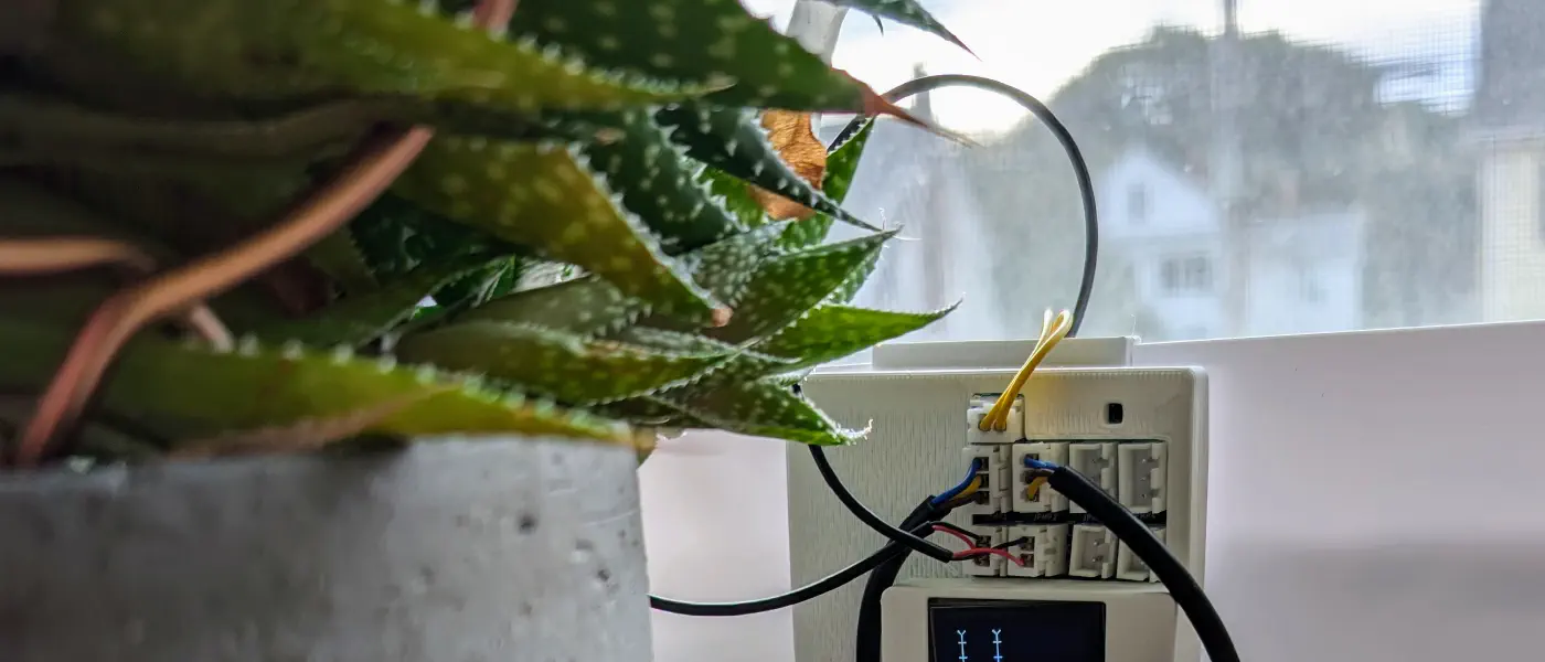
Please see the instructions for how to assemble and set up a Plant133 device hardware.
secrets.ini.example to secrets.ini and set your WiFi credentials, OTA password, and MQTT details.local.ini.example to local.ini and configure your target board environment (e.g., usb_v20 for ESP32-S3 Board v2.x, or usb_spider for ESP32 Board v1.x).cd svelte
npm install./util/check.sh# For Board v2.x (ESP32-S3)
pio run -e usb_v20
# Or for Board v1.x (Classic ESP32)
pio run -e usb_spiderpio run -e usb_v20 -t uploadThe device exposes a JSON API for integration and control:
GET /api/status: Returns system status (temperature, humidity, water level, pump time remaining, MQTT connection, software & hardware versions).GET /api/plants: Returns configuration and status for all plants.PUT /api/plants/{id}: Updates configuration for a specific plant (1–4).GET /api/moisture: Returns current moisture readings, raw ADC counts, dose counts, and watering states.GET /api/wifi / PUT /api/wifi: Get or update WiFi SSID and board name (triggers device restart on update).GET /api/mqtt / PUT /api/mqtt: Get or update MQTT configuration (host, port, mode, SSL/TLS, credentials).POST /test/pump: Run a pump for a specific duration (JSON body: { "pumpId": 1, "duration": 1000 }).POST /api/restart: Restart the device.This project is built using a custom C++ framework for ESP devices:
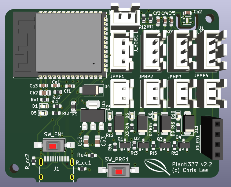
The full KiCAD project and bill of materials (KiCAD/Plant133.csv) for the printed circuit board are in the KiCAD subdirectory. Board v2.x uses an ESP32-S3-WROOM-1-N8R2 module with native USB-C and onboard boot/reset buttons (legacy v1.2/v1.3 ESP32 boards are also supported via build flags).
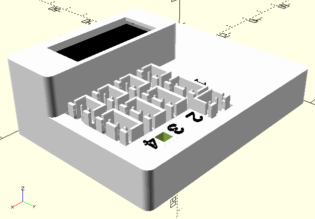
Components are designed in OpenSCAD. Source code and STL models are in the scad subdirectory.
Housing for the PCBA, OLED support bracket, and test fixture (scad/box/).
Covers the water reservoir with cutouts for the EBox, tubing, and wires (scad/reservoir_cover/).
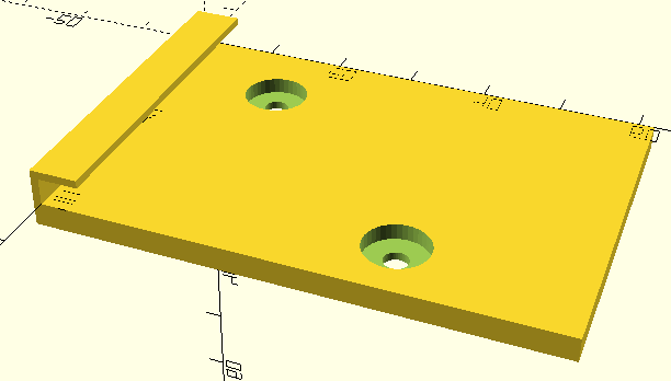
Mounts the box to a water reservoir (scad/ebox_hook/).
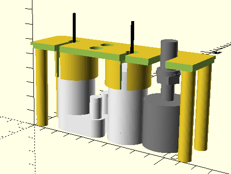
Holds pumps and water level float (scad/reservoir_insert/).
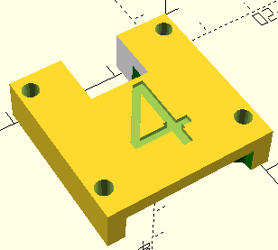
Alignment fixture and edge-support frame for applying solder paste with a PCB stencil (scad/stencil_fixture/).
Holds the watering tube at the sensor location (scad/moisture_sensor_cap/).
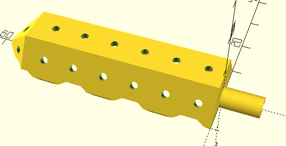
Alternative watering method using a soil spike (scad/spike/).
| Qty | Value | Footprint | References |
|---|---|---|---|
| 6 | 1k | Resistor_SMD:R_0603_1608Metric | Rl1, Rl2, Rl3, Rl4, Rl5, Rl6 |
| 5 | Conn_01x02_Pin | Connector_JST:JST_XH_B2B-XH-A_1x02_P2.50mm_Vertical | JPMP1, JPMP2, JPMP3, JPMP4, JWL1 |
| 4 | 10nF | Capacitor_SMD:C_0603_1608Metric_Pad1.08x0.95mm_HandSolder | Cf1, Cf3, Cf4, Cf5 |
| 4 | 1N4001 | Diode_SMD:D_SMA | D3, D7, D9, D11 |
| 4 | 470 | Resistor_SMD:R_0603_1608Metric | Rt2, Rt3, Rt4, Rt5 |
| 4 | AO3400A | Package_TO_SOT_SMD:SOT-23 | Q1, Q2, Q3, Q4 |
| 4 | Conn_01x03_Pin | Connector_JST:JST_XH_B3B-XH-A_1x03_P2.50mm_Vertical | J_MOIS1, J_MOIS2, J_MOIS3, J_MOIS4 |
| 4 | RED | LED_SMD:LED_0603_1608Metric | D2, D6, D8, D10 |
| 3 | 100nF | Capacitor_SMD:C_0603_1608Metric | Ca1, Ca2, Ca3 |
| 2 | 10k | Resistor_SMD:R_0603_1608Metric | Ru2, Ru4 |
| 2 | 10uF | Capacitor_SMD:C_0805_2012Metric_Pad1.18x1.45mm_HandSolder | Cb2, Cb3 |
| 2 | 2.2k | Resistor_SMD:R_0603_1608Metric | Rf1, Rf2 |
| 2 | 5.1k | Resistor_SMD:R_0603_1608Metric | R_cc1, R_cc2 |
| 2 | SW_Push | Button_Switch_SMD:SW_SPST_FSMSM | SW_EN1, SW_PRG1 |
| 1 | 12k | Resistor_SMD:R_0603_1608Metric | Ru1 |
| 1 | 47uF | Capacitor_SMD:C_0805_2012Metric_Pad1.18x1.45mm_HandSolder | Cc2 |
| 1 | AMS1117-3.3 | Package_TO_SOT_SMD:SOT-223-3_TabPin2 | U3 |
| 1 | BLU | LED_SMD:LED_0603_1608Metric | D1 |
| 1 | Conn_01x04_Socket | Connector_PinSocket_2.54mm:PinSocket_1x04_P2.54mm_Vertical | JOLED1 |
| 1 | ESP32-S3-WROOM-1 | RF_Module:ESP32-S3-WROOM-1 | U2 |
| 1 | Fuse_Small | Diode_SMD:D_0805_2012Metric | F1 |
| 1 | SHTC3 | Sensor_Humidity:Sensirion_DFN-4-1EP_2x2mm_P1mm_EP0.7x1.6mm | U1 |
| 1 | SS14 | Diode_SMD:D_SMA | D4 |
| 1 | USB_C_Receptacle_USB2.0_16P | Connector_USB:USB_C_Receptacle_HRO_TYPE-C-31-M-12 | J1 |
| 1 | YLW | LED_SMD:LED_0603_1608Metric | D5 |
The 59 most common of 61 parts.
It measures 59.6 × 48.3 mm and has 4 copper layers, 2.07 mm thick.
61 parts, built around the ESP32-S3-WROOM-1-N8, SHTC3, AMS1117-3.3 and AO3400A. The full list of its parts is on this page, with links to each part's symbol and footprint where PCBKit's library has them.
From the chl33/Plant133 repository on GitHub, at the commit this page was made from: the board is KiCAD/Plant1337.kicad_pcb and its schematic KiCAD/Plant1337.kicad_sch. PCBKit opens the board in the browser, with nothing to install.
Its repository publishes it under the MIT licence: you may reuse it on that licence's terms (keep the author's notice, and for a copyleft licence share your changes alike).
kokhaie/Smart-Refrigerator-Demo
The KiCad-generated BOM is mirrored into the documentation site under docs/ so it can be published through GitHub Pages.


Carabouille/Alarm_Clock_dawn_simulator
A description of my Alarm clock with dawn simulator for the Fallout event organised By Hackclub


AleksaHeler/FlexNode
FlexNode is a DIY "smart home" system with a single hub and multiple flexible and customizable nodes

electromotif208/pcb-portfolio
👨💻 Electronics Engineer 📺 YouTube: ELECTROMOTIF 🔧 Tools: KiCad, EasyEDA 📡 Domains: Power Supply, ESP32, IoT, Embedded Hardware