4 layers59.6 × 48.3 mm
Plant1337
chl33/Plant133
Firmware, circuit design, and 3D-printable components for an automated plant-watering system.
61 parts6MIT

 chl33/Garage1331
A DIY device for garage door automation
Garage133 is an open-source printed circuit board by chl33, from the chl33/Garage133 repository on GitHub, published under the MIT licence. It is a 4-layer board of 93.3 × 40.7 mm with 60 parts on 70 nets, routed with 476 tracks and 112 vias.
It is built around the ESP32-S3-WROOM-1-N8, SHTC3 and AMS1117-3.3, with the B5817WS-TP, MMBT4403 and SS14 among its other parts. Its parts include 10 resistors, 3 ICs, 3 transistors, 2 diodes and 2 switches. It belongs with the home automation and IoT boards and the ESP32 boards of this library.


Garage133 is a DIY garage door automation and monitoring system based on the ESP32 / ESP32-S3. It provides the capability to remotely control up to two garage doors, monitor their state (open/closed), detect vehicle presence using a multi-sonar sensor array, measure environmental conditions (temperature/humidity), and detect motion within the garage.
The system integrates seamlessly with Home Assistant via MQTT Discovery and provides a modern, responsive Svelte-based Web Interface for real-time monitoring and configuration.
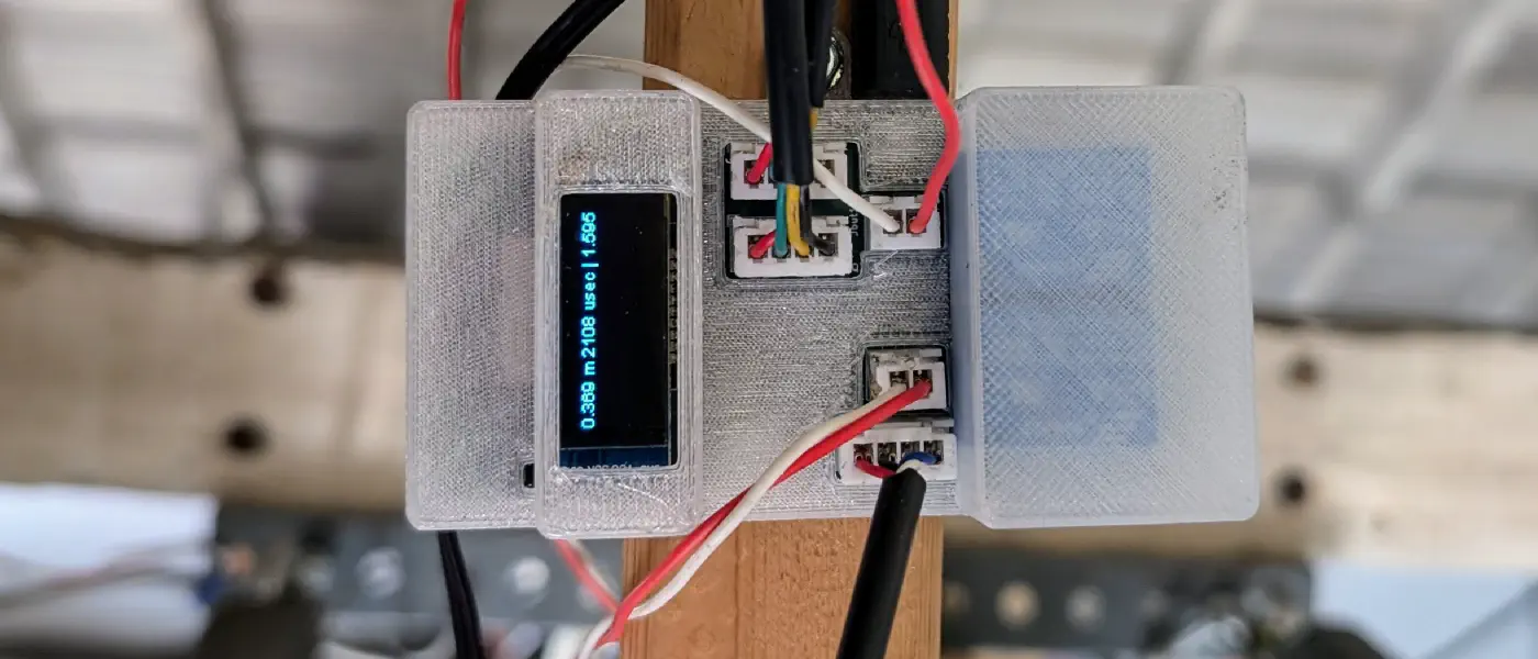
analysis/hmm_to_svg.py) and streamlined characterization workflow in analysis/retrain.py.chl33/og3@^0.7.0, chl33/og3x-oled@^0.6.1, chl33/og3x-shtc3@^0.6.0).probOpen, probCar, probEmpty) to Home Assistant via MQTT Discovery.svelteesp32 to v3.2.5 and upgraded GitHub Actions workflows to Node 22 for reliable, deterministic builds.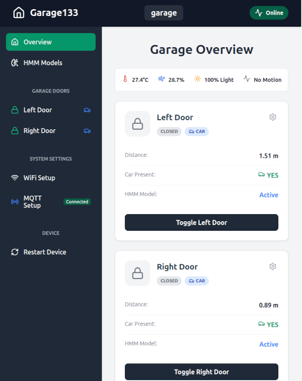
Garage133 is designed for the Board v3.1 / v3.0 (ESP32-S3). Earlier Board v1/v2 (Classic ESP32) revisions have been retired.
| Component | Board v3.1 / v3.0 (ESP32-S3) | Description |
|---|---|---|
| Relay (Left) | GPIO 10 | Left Garage Door Relay Command |
| Relay (Right) | GPIO 11 | Right Garage Door Relay Command |
| Sonar 1 Trig / Echo (Left) | GPIO 1 / GPIO 5 | Primary Left Ultrasonic Sensor |
| Sonar 2 Trig / Echo (Left) | GPIO 3 / GPIO 7 | Secondary Left Ultrasonic Sensor |
| Sonar 1 Trig / Echo (Right) | GPIO 2 / GPIO 6 | Primary Right Ultrasonic Sensor |
| Sonar 2 Trig / Echo (Right) | GPIO 4 / GPIO 15 | Secondary Right Ultrasonic Sensor |
| PIR Sensor | GPIO 12 | PIR Motion Detection |
| Light Sensor | GPIO 12 | Analog Light Level |
| I2C SDA / SCL | GPIO 8 / GPIO 9 | SHTC3 Sensor & OLED Display |
Note: Pin definitions are configured in src/main.cpp [blocked].
This repository includes files for fabricating the custom PCB and 3D printed case:
KiCAD/ directory.scad/ directory.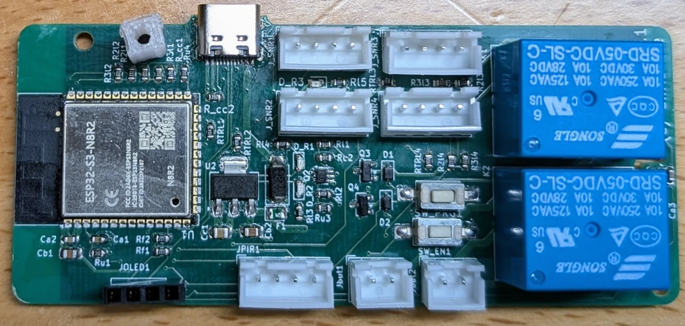
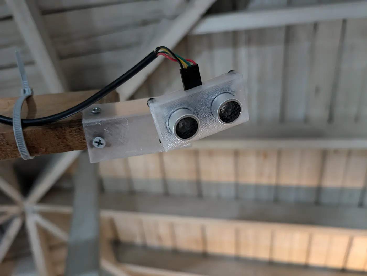
Sonar sensor mount design is also published on Printables.
Clone the repository:
git clone https://github.com/chl33/Garage133.git
cd Garage133
Build the Web Interface: Generate the C++ header containing the compiled Svelte SPA:
./build-svelte.shConfiguration: Copy the example configuration files and customize your settings:
cp secrets.ini.example secrets.ini
cp local.ini.example local.ini
Note: WiFi and MQTT credentials can also be configured via the captive portal on first boot (when connected to the garage133 AP) or through the web dashboard settings page.
Build and Flash: Connect your board via USB for the initial flash:
pio run -e usb_s3 --target uploadpio run -e wifi_s3 --target uploadNavigate to the device's IP address in your web browser:
The device automatically publishes Home Assistant MQTT Discovery topics:
left_door, right_door (Open/Close control & state feedback)temperature, humidity, light, prob_open, prob_car, prob_emptycar (vehicle presence per bay), door, motionThe analysis/ directory contains Python tools to train and evaluate multi-sonar classification models:
For background and detailed design notes on this project, check out the Garage133 Blog Post.
This project is licensed under the MIT License - see the LICENSE file for details.
| Qty | Value | Footprint | References |
|---|---|---|---|
| 9 | 1k | Resistor_SMD:R_0603_1608Metric | Rl1, Rl2, Rl3, Rl4, Rl5, RTRL1, RTRL2, RTRL3, RTRL4 |
| 6 | 2.2k | Resistor_SMD:R_0603_1608Metric | R2l1, R2l2, R2l3, R2l4, Rf1, Rf2 |
| 5 | Conn_01x04_Pin | Connector_JST:JST_XH_B4B-XH-A_1x04_P2.50mm_Vertical | J_SNR1, J_SNR2, J_SNR3, J_SNR4, JPIR1 |
| 4 | 10k | Resistor_SMD:R_0603_1608Metric | Ru1, Ru2, Ru3, Ru4 |
| 4 | 3.3k | Resistor_SMD:R_0603_1608Metric | R3l1, R3l2, R3l3, R3l4 |
| 3 | 100nF | Capacitor_SMD:C_0603_1608Metric | Ca1, Ca2, Ca3 |
| 2 | 10uF | Capacitor_SMD:C_0805_2012Metric_Pad1.18x1.45mm_HandSolder | Cb1, Cb2 |
| 2 | 5.1k | Resistor_SMD:R_0603_1608Metric | R_cc1, R_cc2 |
| 2 | B5817WS-TP | Diode_SMD:D_SOD-323 | D1, D2 |
| 2 | Conn_01x02 | Connector_JST:JST_XH_B2B-XH-A_1x02_P2.50mm_Vertical | Jbut1, Jbut2 |
| 2 | MMBT4403 | Package_TO_SOT_SMD:SOT-23 | Q3, Q4 |
| 2 | SANYOU_SRD_Form_C | Relay_THT:Relay_SPDT_SANYOU_SRD_Series_Form_C | K1, K2 |
| 2 | SW_Push | Button_Switch_SMD:SW_SPST_FSMSM | SW_EN1, SW_PRG1 |
| 1 | 0.5A | Diode_SMD:D_0805_2012Metric | F1 |
| 1 | 47uF | Capacitor_SMD:C_0805_2012Metric_Pad1.18x1.45mm_HandSolder | Cc1 |
| 1 | AMS1117-3.3 | Package_TO_SOT_SMD:SOT-223-3_TabPin2 | U2 |
| 1 | BLU | LED_SMD:LED_0603_1608Metric | D_R2 |
| 1 | Conn_01x04_Socket | Connector_PinSocket_2.54mm:PinSocket_1x04_P2.54mm_Vertical | JOLED1 |
| 1 | ESP32-S3-WROOM-1 | RF_Module:ESP32-S3-WROOM-1 | U1 |
| 1 | RED | LED_SMD:LED_0603_1608Metric | D_R1 |
| 1 | SHTC3 | Sensor_Humidity:Sensirion_DFN-4-1EP_2x2mm_P1mm_EP0.7x1.6mm | U3 |
| 1 | SS14 | Diode_SMD:D_SMA | DUSB1 |
| 1 | UMH3N | Package_TO_SOT_SMD:SOT-363_SC-70-6 | Q2 |
| 1 | USB_C_Receptacle_USB2.0_16P | Connector_USB:USB_C_Receptacle_HRO_TYPE-C-31-M-12 | J1 |
| 1 | YLW | LED_SMD:LED_0603_1608Metric | D_R3 |
The 57 most common of 60 parts.
It measures 93.3 × 40.7 mm and has 4 copper layers, 1.6 mm thick.
60 parts, built around the ESP32-S3-WROOM-1-N8, SHTC3, AMS1117-3.3 and B5817WS-TP. The full list of its parts is on this page, with links to each part's symbol and footprint where PCBKit's library has them.
From the chl33/Garage133 repository on GitHub, at the commit this page was made from: the board is KiCAD/Garage133.kicad_pcb and its schematic KiCAD/Garage133.kicad_sch. PCBKit opens the board in the browser, with nothing to install.
Its repository publishes it under the MIT licence: you may reuse it on that licence's terms (keep the author's notice, and for a copyleft licence share your changes alike).
chl33/Plant133
Firmware, circuit design, and 3D-printable components for an automated plant-watering system.

kokhaie/Smart-Refrigerator-Demo
The KiCad-generated BOM is mirrored into the documentation site under docs/ so it can be published through GitHub Pages.


mornepousse/KeSp_dongle
Recepteur USB 2.4 GHz du clavier Niphargus et de la souris Conchodytes — ESP32-S3 / ESP32-P4, nRF24L01+, format M.2 Key B
