
4 layers80 × 80 mm
Telemetry
chithigun23/ANUFS-Telemetry
To use custom hardware to measure parameters and dynamics of an ICE Formula SAE car.
159 parts

An update to the Accelerator Pedal Position Plausibility Device to remain compliant with the use of a paddle shift system.
Apppd is an open-source printed circuit board by chithigun23, from the chithigun23/ANUFS-APPPD repository on GitHub. It is a 4-layer board of 58.9 × 48.4 mm with 103 parts on 83 nets, routed with 620 tracks and 195 vias.
It is built around the TCAN337D, AP2112K-3.3 and USBLC6-2SC6, with the AQ1005-01ETG, AO3400A and PMEG2010BER among its other parts. Its parts include 30 resistors, 27 capacitors, 13 diodes, 7 ICs and 4 connectors. It belongs with the audio and music boards and the STM32 boards of this library.


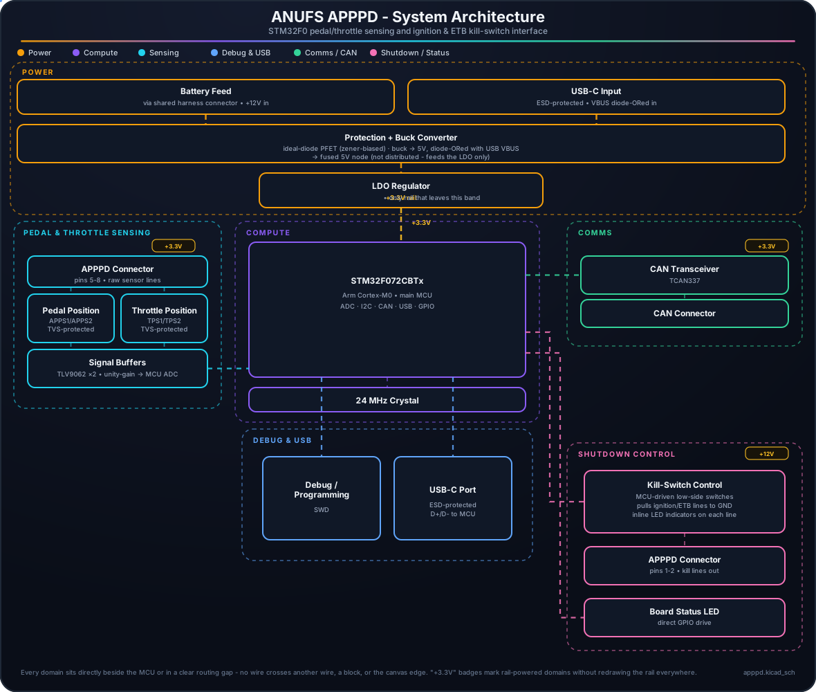
Accelerator pedal position (APPS) and throttle position (TPS) sensor interface for the ANUFS vehicle, with dual-redundant sensing, ignition/electronic-throttle-body kill-switch control, and CAN reporting. A single 8-pin harness connector carries power in, both raw sensor pairs, and the two kill lines out.
U6 (LMR33610), which bucks it to 5V. That 5V is diode-ORed with USB-C VBUS onto a single fused node that only ever feeds U1 (AP2112K-3.3) - the +3.3V rail is the only supply that leaves the power stage, reaching the MCU, CAN transceiver, both op-amps and the status LED.AQ1005-01ETG TVS array. U5 and U7 (TLV9062 dual op-amps) buffer them with unity gain straight into the MCU's ADC inputs.U2, an STM32F072CBTx (Cortex-M0), is the hub, clocked from a 24MHz crystal (Y1).Q1 for ignition, Q2 for electronic throttle body) that pull the corresponding harness line to ground to trip the external kill relay. Each line has an inline LED (D3, D5) that lights while its kill switch is active, so the cut state is visible without a laptop. A separate GPIO-driven LED (LED1) gives a general board heartbeat/fault indication.TCAN337 transceiver (U4) puts pedal/throttle status and kill-line faults on the vehicle CAN bus via J4.J5, ESD-protected by U3) for bench debug/firmware and D+/D- to the MCU; J1 (Conn_SWD) for programming.The diagram above is a live SVG: dashed lines show active power/signal paths, and the small dots trace the flow through each domain (open assets/architecture.svg directly if your viewer doesn't animate it).
| Qty | Value | Footprint | References |
|---|---|---|---|
| 13 | 100nF | Capacitor_SMD:C_0402_1005Metric_Pad0.74x0.62mm_HandSolder | C5, C6, C7, C8, C10, C12, C18, C26, C27, C28, C29, C30, C31 |
| 8 | 100k | Resistor_SMD:R_0402_1005Metric_Pad0.72x0.64mm_HandSolder | R9, R10, R11, R15, R29, R30, R31, R32 |
| 7 | 150 | Resistor_SMD:R_0402_1005Metric_Pad0.72x0.64mm_HandSolder | R7, R14, R19, R26, R27, R28, R33 |
| 5 | 1uF | Capacitor_SMD:C_0402_1005Metric_Pad0.74x0.62mm_HandSolder | C2, C3, C11, C17, C23 |
| 4 | 10k | Resistor_SMD:R_0402_1005Metric_Pad0.72x0.64mm_HandSolder | R1, R4, R5, R6 |
| 4 | 10uF | Capacitor_SMD:C_0402_1005Metric_Pad0.74x0.62mm_HandSolder | C1, C9, C15, C24 |
| 4 | 150k | Resistor_SMD:R_0402_1005Metric_Pad0.72x0.64mm_HandSolder | R38, R39, R40, R41 |
| 4 | AQ1005-01ETG | apppd:AQ1005-01ETG | D4, D6, D9, D12 |
| 4 | MountingHole_Pad | H1, H2, H3, H4 | |
| 2 | 1k | Resistor_SMD:R_0402_1005Metric_Pad0.72x0.64mm_HandSolder | R21, R22 |
| 2 | 22uF | Capacitor_SMD:C_0402_1005Metric_Pad0.74x0.62mm_HandSolder | C19, C20 |
| 2 | 5.1k | Resistor_SMD:R_0402_1005Metric_Pad0.72x0.64mm_HandSolder | R2, R3 |
| 2 | 8pF | Capacitor_SMD:C_0402_1005Metric_Pad0.74x0.62mm_HandSolder | C13, C14 |
| 2 | AO3400A | Package_TO_SOT_SMD:SOT-23 | Q1, Q2 |
| 2 | BPS | TestPoint:TestPoint_Keystone_5000-5004_Miniature | TP3, TP4 |
| 2 | LED | apppd:AP2012EC | D3, D5 |
| 2 | PMEG2010BER | Diode_SMD:Nexperia_CFP3_SOD-123W | D10, D11 |
| 2 | PMEG6010ER | Diode_SMD:Nexperia_CFP3_SOD-123W | D13, D14 |
| 2 | TLV9062xD | Package_SO:SOIC-8_3.9x4.9mm_P1.27mm | U5, U7 |
| 1 | +3V3 | TestPoint:TestPoint_THTPad_D2.0mm_Drill1.0mm | TP7 |
| 1 | 10K | Resistor_SMD:R_0402_1005Metric_Pad0.72x0.64mm_HandSolder | R8 |
| 1 | 220nF | Capacitor_SMD:C_0402_1005Metric_Pad0.74x0.62mm_HandSolder | C16 |
| 1 | 24.9k | Resistor_SMD:R_0402_1005Metric_Pad0.72x0.64mm_HandSolder | R12 |
| 1 | 2601-1102 | apppd:WAGO-2601-1102 | J4 |
| 1 | 300mA Polyfuse | Fuse:Fuse_0805_2012Metric_Pad1.15x1.40mm_HandSolder | F1 |
| 1 | 470 | Resistor_SMD:R_0402_1005Metric_Pad0.72x0.64mm_HandSolder | R20 |
| 1 | 8.2uH, 86m | Inductor_SMD:L_Vishay_IHLP-2525 | L1 |
| 1 | ABM8AIG-24.000MHz-8-2Z-T | apppd:ABM8AIG-24.000MHZ-8-2Z-T | Y1 |
| 1 | AP2112K-3.3 | Package_TO_SOT_SMD:SOT-23-5_HandSoldering | U1 |
| 1 | APPPD Connector | apppd:MOLEX_430450800 | J2 |
| 1 | BOOT0 | apppd:SW-SMD_L3.9-W3.0-P4.45 | SW2 |
| 1 | BZT52-C15S-AU_R1_000A1 | Diode_SMD:D_SOD-323_HandSoldering | D1 |
| 1 | CAN+ | TestPoint:TestPoint_THTPad_D2.0mm_Drill1.0mm | TP5 |
| 1 | CAN- | TestPoint:TestPoint_THTPad_D2.0mm_Drill1.0mm | TP6 |
| 1 | Conn_SWD | Connector_PinHeader_2.54mm:PinHeader_1x04_P2.54mm_Vertical | J1 |
| 1 | FerriteBead | Capacitor_SMD:C_0603_1608Metric_Pad1.08x0.95mm_HandSolder | FB1 |
| 1 | GND | TestPoint:TestPoint_THTPad_D2.0mm_Drill1.0mm | TP9 |
| 1 | LMR33610ADDAR | apppd:LMR33610_HSOP8_SolidGND | U6 |
| 1 | NRST | apppd:SW-SMD_L3.9-W3.0-P4.45 | SW1 |
| 1 | PMV100EPA | Package_TO_SOT_SMD:SOT-23 | Q3 |
| 1 | SMF16A | apppd:SMF16A | D2 |
| 1 | STM32F072CBTx | Package_QFP:LQFP-48_7x7mm_P0.5mm | U2 |
| 1 | TCAN337 | Package_SO:SOIC-8_3.9x4.9mm_P1.27mm | U4 |
| 1 | TPS1 | TestPoint:TestPoint_Keystone_5000-5004_Miniature | TP1 |
| 1 | TPS2 | TestPoint:TestPoint_Keystone_5000-5004_Miniature | TP2 |
| 1 | USBLC6-2SC6 | Package_TO_SOT_SMD:SOT-23-6 | U3 |
| 1 | USB_C_Receptacle_USB2.0_16P | apppd:USB-C-SMD_TYPE-C-16PIN-2MD-073 | J5 |
| 1 | VIN_LDO | TestPoint:TestPoint_THTPad_D2.0mm_Drill1.0mm | TP8 |
| 1 | XL-2012SURUGC | apppd:XL-2012SURUGC | LED1 |
chithigun23/ANUFS-Telemetry
To use custom hardware to measure parameters and dynamics of an ICE Formula SAE car.

chithigun23/ANUFS-BSPD-2026
ANUFS's BSPD for 2026 Formula SAE ICE Car. The goal of this project is to be AEC-Q100/Q101/Q200 compliant.


H2O-Tnp/ganglia
Ganglia is an open BLDC / brushed motor driver platform — custom PCB hardware plus STM32 firmware that runs a real-time control loop on top of FreeRTOS.

joeycastillo/Sensor-Watch
A board replacement for the classic Casio F-91W wristwatch


lollokara/HomeKey-ESP32-PCB
HomeKey-ESP32-PCB A miniaturized, wall-mountable HomeKey reader board

It measures 58.9 × 48.4 mm and has 4 copper layers, 1.6 mm thick.
103 parts, built around the TCAN337D, AP2112K-3.3, USBLC6-2SC6 and AQ1005-01ETG. The full list of its parts is on this page, with links to each part's symbol and footprint where PCBKit's library has them.
From the chithigun23/ANUFS-APPPD repository on GitHub, at the commit this page was made from: the board is apppd.kicad_pcb and its schematic apppd.kicad_sch. PCBKit opens the board in the browser, with nothing to install.
Its repository states no licence, so its author keeps all rights: ask chithigun23 before reusing the design.