
4 layers58.9 × 48.4 mm
Apppd
chithigun23/ANUFS-APPPD
An update to the Accelerator Pedal Position Plausibility Device to remain compliant with the use of a paddle shift system.
103 parts

ANUFS's BSPD for 2026 Formula SAE ICE Car. The goal of this project is to be AEC-Q100/Q101/Q200 compliant.
Bspd is an open-source printed circuit board by chithigun23, from the chithigun23/ANUFS-BSPD-2026 repository on GitHub. It is a 4-layer board of 75.5 × 62 mm with 120 parts on 61 nets, routed with 1,102 tracks and 518 vias.
It is built around the SN74LVC2G14DBVR, LM1117MP-5.0 and SN74HC74DR(LX), with the AP2012EC, 3313J-1-203E and AQ1005-01ETG among its other parts. Its parts include 46 resistors, 27 capacitors, 15 diodes, 8 ICs and 2 transistors.


Brake System Plausibility Device — analog detection, timed qualification, latched shutdown.
This board monitors two throttle-position signals (TPS1/TPS2) and brake pressure (BPS). A persistent sensor-range fault, or sustained hard braking with throttle above 10%, removes the board's supply to the vehicle shutdown circuit.
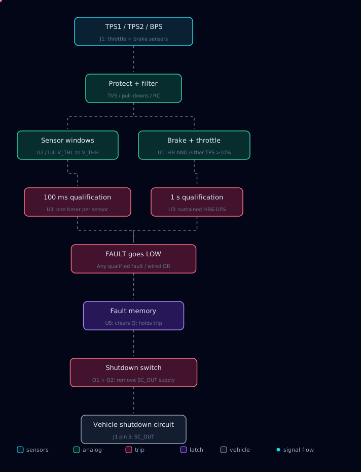
V_THL and V_THH. In parallel, U1 detects hard braking AND either TPS channel above its calibrated 10% threshold. TPS2 uses the opposite comparator polarity to TPS1, matching the schematic's opposite sensor slopes.HB&10% for approximately 1 second. A brief excursion that recovers sufficiently before the timing threshold does not trip the latch; RC history affects closely spaced excursions.FAULT. Any qualified fault pulls this normally high net low, asserting U5's asynchronous clear. U5 Q falls and stays low after the original fault disappears.OUTPUT turns Q1 off; R30 pulls Q2's gate toward its source, turning the P-channel switch off. The board stops supplying +12 V to SC_OUT on J1 pin 5. External vehicle circuitry determines the resulting shutdown action.| Condition | Qualified FAULT | U5 Q / OUTPUT | SC_OUT supply |
|---|---|---|---|
| Initialized, healthy, no previous trip | High | High | Enabled |
| Fault present, timer has not reached threshold | High | Remains high if previously enabled | Enabled |
| Either fault path reaches its timer threshold | Low | Forced low | Disabled |
| Sensor condition recovers after a trip | Returns high after timer recovery | Remains low | Disabled |
| Power cycled with faults absent | Power-on preset initializes U5 | Returns high | Enabled after initialization |
The U7 Schmitt-trigger circuit with R32/C19/C20 generates the power-on preset. This design does not use a software reset or automatically re-enable just because a fault clears.
| Block | Implementation |
|---|---|
| Logic supply | U6 LM1117-5.0 regulates +12 V to +5 V; D5 provides supply transient suppression. |
| Sensor limits | SW1/SW2 select fixed or variable window references. Fixed net names are +0V45 and +4V7; RV4/RV5 provide adjustable alternatives. |
| Operating thresholds | RV1 sets HB_THRESH; RV2/RV3 set TPS1_THRESH / TPS2_THRESH. Calibrate these against the actual sensors. |
| Timing reference | +2V5 feeds U3; sensor timers use 150 kΩ / 1 µF; overlap timing uses R7 + R8 = 300 kΩ with C1 = 4.7 µF. |
| Indicators | U8/U9 buffer condition indicators D10–D15. U5's complementary output drives latch indicator D9 through R39. |
| Pin | Net | Role |
|---|---|---|
| 1 | +12V | Board and switched-output supply |
| 2 | Unconnected | No connection |
| 3 | GND | Board ground |
| 4 | /SENS_0V | Sensor return, joined to GND through R46 (0 Ω) |
| 5 | SC_OUT | Switched shutdown-circuit supply |
| 6 | BPS_RAW | Brake-pressure input |
| 7 | TPS2_RAW | Throttle-position channel 2 |
| 8 | TPS1_RAW | Throttle-position channel 1 |
Animation generated using Dashmotion (MIT); attribution is retained in docs/DASHMOTION-LICENSE.txt. The diagram assets have no external runtime dependencies.
| Qty | Value | Footprint | References |
|---|---|---|---|
| 16 | 100nF | Capacitor_SMD:C_0805_2012Metric_Pad1.18x1.45mm_HandSolder | C8, C9, C10, C11, C12, C13, C14, C17, C18, C21, C22, C23, C24, C25, C26, C27 |
| 14 | 150k | Resistor_SMD:R_0805_2012Metric_Pad1.20x1.40mm_HandSolder | R3, R6, R7, R8, R11, R12, R14, R16, R18, R19, R22, R27, R32, R33 |
| 8 | 500 | Resistor_SMD:R_0805_2012Metric_Pad1.20x1.40mm_HandSolder | R31, R39, R40, R41, R42, R43, R44, R45 |
| 7 | 5.1k | Resistor_SMD:R_0805_2012Metric_Pad1.20x1.40mm_HandSolder | R2, R4, R5, R9, R13, R17, R24 |
| 7 | AP2012EC | bspd:AP2012EC | D9, D10, D11, D12, D13, D14, D15 |
| 6 | 1uF | Capacitor_SMD:C_0805_2012Metric_Pad1.18x1.45mm_HandSolder | C2, C3, C4, C5, C6, C7 |
| 5 | 10M | Resistor_SMD:R_0805_2012Metric_Pad1.20x1.40mm_HandSolder | R34, R35, R36, R37, R38 |
| 5 | 3313J-1-203E | bspd:3313J-1-203E | RV1, RV2, RV3, RV4, RV5 |
| 4 | 5.49k | Resistor_SMD:R_0805_2012Metric_Pad1.20x1.40mm_HandSolder | R1, R10, R15, R25 |
| 4 | MountingHole_Pad | MountingHole:MountingHole_3.2mm_M3_ISO14580_Pad | H1, H2, H3, H4 |
| 4 | TLV1704AIPWR | bspd:TLV1704 | U1, U2, U3, U4 |
| 3 | 4.7uF | Capacitor_SMD:C_0805_2012Metric_Pad1.18x1.45mm_HandSolder | C1, C19, C20 |
| 3 | AQ1005-01ETG | Diode_SMD:D_SOD-882 | D2, D3, D4 |
| 3 | LOGO | LOGO | G***, G***, G*** |
| 2 | 10uF | Capacitor_SMD:C_0805_2012Metric_Pad1.18x1.45mm_HandSolder | C15, C16 |
| 2 | 1N4148W | Diode_SMD:D_SOD-123 | D1, D6 |
| 2 | 49.9k | Resistor_SMD:R_0805_2012Metric_Pad1.20x1.40mm_HandSolder | R28, R29 |
| 2 | 54.9k | Resistor_SMD:R_0805_2012Metric_Pad1.20x1.40mm_HandSolder | R20, R30 |
| 2 | CJS-1200TB1 | bspd:CJS-1200TB1 | SW1, SW2 |
| 2 | S1B-13-F | bspd:S1B-13-F | D7, D8 |
| 1 | +0V45 | TestPoint:TestPoint_Keystone_5000-5004_Miniature | TP4 |
| 1 | +1V25 | TestPoint:TestPoint_Keystone_5000-5004_Miniature | TP5 |
| 1 | +2V5 | TestPoint:TestPoint_Keystone_5000-5004_Miniature | TP6 |
| 1 | +4V5 | TestPoint:TestPoint_Keystone_5000-5004_Miniature | TP7 |
| 1 | 0 | Resistor_SMD:R_0805_2012Metric_Pad1.20x1.40mm_HandSolder | R46 |
| 1 | 2.61k | Resistor_SMD:R_0805_2012Metric_Pad1.20x1.40mm_HandSolder | R23 |
| 1 | 21.5k | Resistor_SMD:R_0805_2012Metric_Pad1.20x1.40mm_HandSolder | R21 |
| 1 | 7.15k | Resistor_SMD:R_0805_2012Metric_Pad1.20x1.40mm_HandSolder | R26 |
| 1 | AO3400A | Package_TO_SOT_SMD:SOT-23 | Q1 |
| 1 | AO3401A | Package_TO_SOT_SMD:SOT-23 | Q2 |
| 1 | BPS | TestPoint:TestPoint_Keystone_5000-5004_Miniature | TP3 |
| 1 | Conn_02x04_Counter_Clockwise | bspd:WirePad_2x04_P3.0mm | J1 |
| 1 | LM1117MP-5.0 | Package_TO_SOT_SMD:SOT-223-3_TabPin2 | U6 |
| 1 | SMBJ16A | bspd:SMBJ16A | D5 |
| 1 | SN74AHC14DBR | bspd:SN74AHC14DBR | U10 |
| 1 | SN74HC74DR | bspd:SN74HC74DR | U5 |
| 1 | SN74LVC2G14DBVR | bspd:SN74LVC2G14DBVR | U7 |
| 1 | TPS1 | TestPoint:TestPoint_Keystone_5000-5004_Miniature | TP1 |
| 1 | TPS2 | TestPoint:TestPoint_Keystone_5000-5004_Miniature | TP2 |
chithigun23/ANUFS-APPPD
An update to the Accelerator Pedal Position Plausibility Device to remain compliant with the use of a paddle shift system.

chithigun23/ANUFS-Telemetry
To use custom hardware to measure parameters and dynamics of an ICE Formula SAE car.

everettpenne/PFMV4_Prelim_Files
PFM Controller V4 files for independent design review. For application controlling the Limiter, HVPS, and Transrex supplies.


gallicchio/AMOD-and-RFMOD
The tutorial's 2x12 adapter (/mudd/133electronics/icepi-zero-dac-adc/adapterboard/) with a 2 x 6 right-angle Pmod socket on a 15 mm extension of its right-hand end, so an Icepi Zero can drive AMOD-A's and RF-MOD's Pmod…

It measures 75.5 × 62 mm and has 4 copper layers, 1.6 mm thick.
120 parts, built around the SN74LVC2G14DBVR, LM1117MP-5.0, SN74HC74DR(LX) and AP2012EC. The full list of its parts is on this page, with links to each part's symbol and footprint where PCBKit's library has them.
From the chithigun23/ANUFS-BSPD-2026 repository on GitHub, at the commit this page was made from: the board is bspd-kicad/bspd.kicad_pcb and its schematic bspd-kicad/bspd.kicad_sch. PCBKit opens the board in the browser, with nothing to install.
Its repository states no licence, so its author keeps all rights: ask chithigun23 before reusing the design.