12 layers280 × 111.2 mm
Fpga candelabra
chipsalliance/rocket-pcb
PCB libraries and templates for rocket-chip based FPGA/ASIC designs
738 parts21Apache-2.0

 chipsalliance/rocket-pcb21
PCB libraries and templates for rocket-chip based FPGA/ASIC designs
Pmod microsd is an open-source printed circuit board by chipsalliance, from the chipsalliance/rocket-pcb repository on GitHub, published under the Apache-2.0 licence. It is a 4-layer board of 25.4 × 15.2 mm with 23 parts on 15 nets, routed with 197 tracks and 63 vias.
It is built around the RCLAMP0524P, NCD1206O1 and NCD1206Y1, with the PZ254R-12-12P among its other parts. Its parts include 12 resistors, 4 capacitors, 3 ICs, 2 diodes and 2 connectors.


The Pmod MicroSD provides a microSD card slot to any board that has 3.3V logic and is pin compatible with a 12-pin Pmod port capable of SPI communication.
This board is specially designed to adapt to VCU118, and the pull-up resistor for SDIO is modified to 330 ohm.
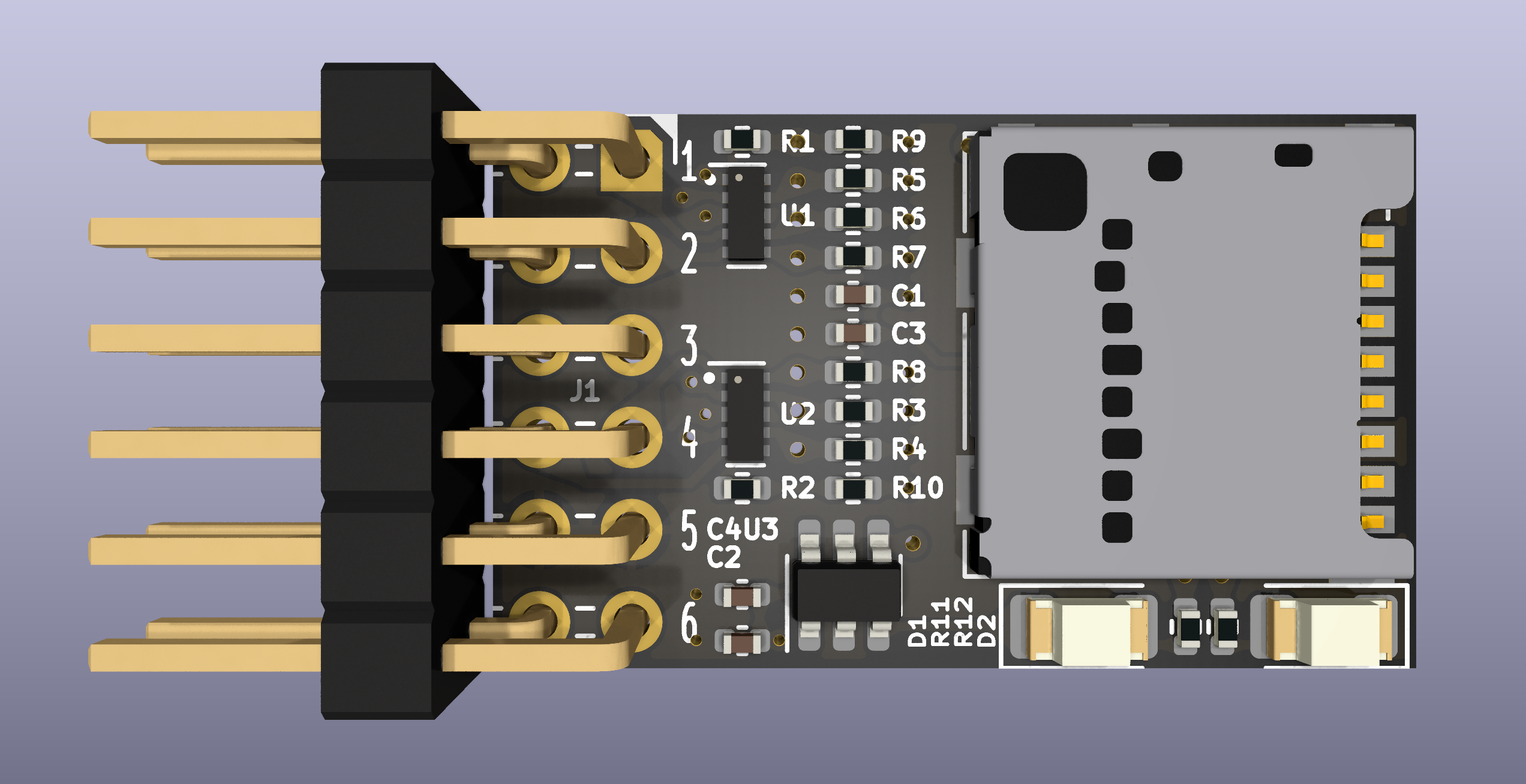
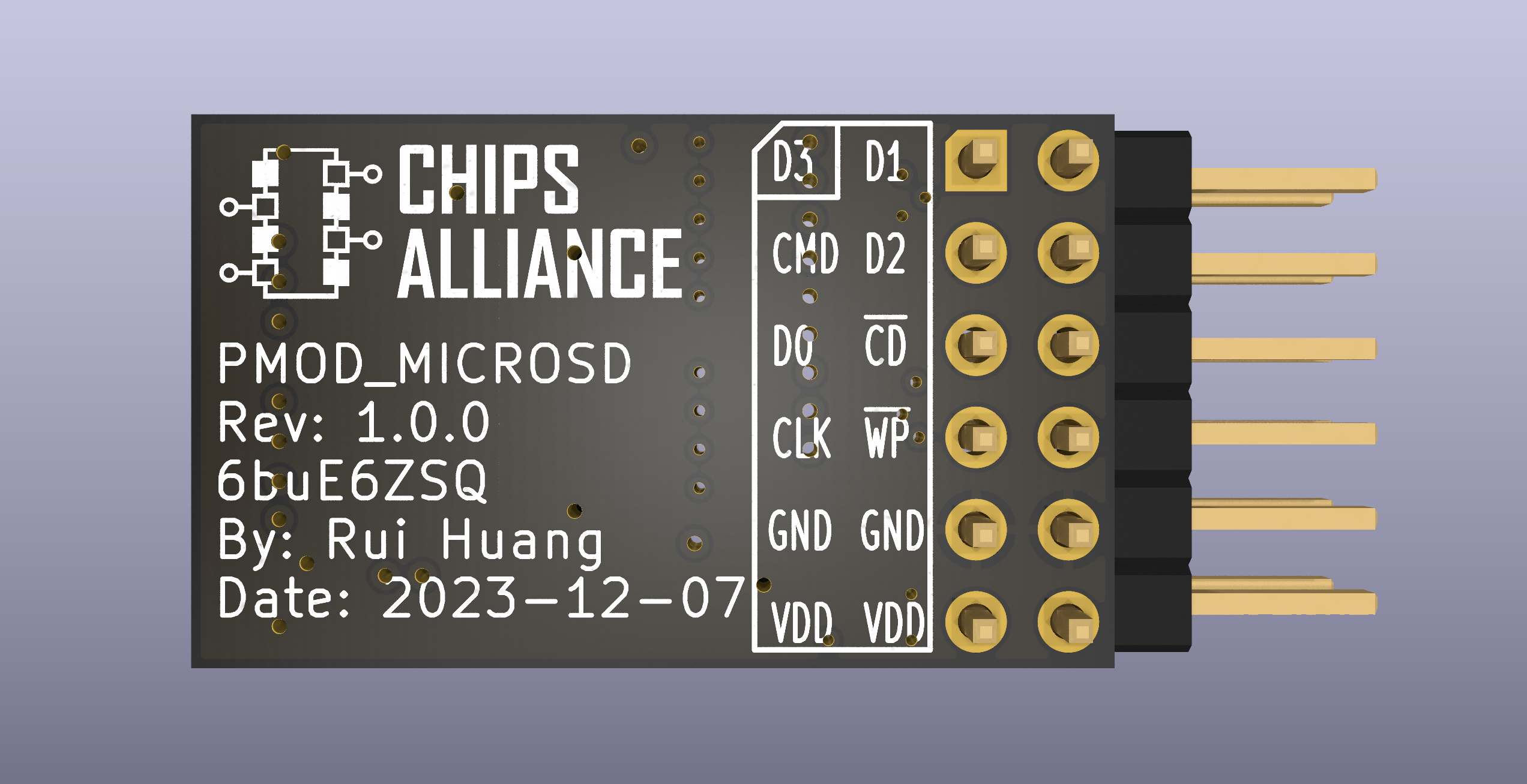
This design complies with Digilent Pmod™ Interface Specification 1.2.0.
Note that the pin sequence numbers on the digilent PMOD specification are inconsistent with the PMOD pin sequence numbers of AMD VCU118 on the document. Essentially they are the same, but the numbering of AMD VCU118 uses a double-column staggered odd-even arrangement. Here is their mapping relationship.
| PMOD PIN | VCU118 PIN | SDIO FUNCTION | SPI FUNCTION |
|---|---|---|---|
| 1 | 1 | DAT3(D3) | #CS |
| 2 | 3 | CMD | MOSI |
| 3 | 5 | DAT0(D0) | MISO |
| 4 | 7 | CLK | SCLK(SCK) |
| 5 | 9 | GND | GND |
| 6 | 11 | 3P3V(VDD) | 3P3V(VDD) |
| 7 | 2 | DAT1(D1) | NC |
| 8 | 4 | DAT2(D2) | NC |
| 9 | 6 | #DET(#CD) | #DET(#CD) |
| 10 | 8 | #WP | #WP |
| 11 | 10 | GND | GND |
| 12 | 12 | 3P3V(VDD) | 3P3V(VDD) |
There are two LEDs on the PCB, the yellow one is the card detection indicator and the orange one is the power indicator.
| LED | COLOR | FUNCTION | ON | OFF |
|---|---|---|---|---|
| 1 | Yellow | Card detection indicator | MicroSD Card inserted | No MicroSD card |
| 2 | Orange | Power indicator | Power on | Power off |
Among them, the #WP signal is constant high level. If the WP signal is
low, please check the power supply and there may be a fault.
| NAME | HIGH | LOW |
|---|---|---|
| #DET(#CD) | No MicroSD card | MicroSD Card inserted |
| #WP | Write protect is off | This state is impossible |
Install kicad 8, cmake, ninja.
cmake -G Ninja -B build
cmake --build build
If you only need to generate a pdf of the schematic or pcb,
cmake --build build --target pdfIf you need to generate complete production data,
cmake --build build --target production| Qty | Value | Footprint | References |
|---|---|---|---|
| 5 | 330 | Resistor_SMD:R_0402_1005Metric | R3, R4, R5, R6, R7 |
| 3 | 10k | Resistor_SMD:R_0402_1005Metric | R8, R9, R10 |
| 2 | 100n | Capacitor_SMD:C_0402_1005Metric | C3, C4 |
| 2 | 10u | Capacitor_SMD:C_0402_1005Metric | C1, C2 |
| 2 | 200 | Resistor_SMD:R_0402_1005Metric | R1, R2 |
| 2 | 6.8k | Resistor_SMD:R_0402_1005Metric | R11, R12 |
| 2 | RCLAMP0524P | CHIPSAlliance_Package_SON:USON-10_2.5x1.0mm_P0.5mm | U1, U2 |
| 1 | AIP74LVC1T45GB236TR | CHIPSAlliance_Package_TO_SOT_SMD:SOT-23-6 | U3 |
| 1 | Micro_SD_Card_Det2 | CHIPSAlliance_Connector:microSD_HC_Molex_104031-0811 | J2 |
| 1 | NCD1206O1 | LED_SMD:LED_1206_3216Metric | D2 |
| 1 | NCD1206Y1 | LED_SMD:LED_1206_3216Metric | D1 |
| 1 | PZ254R-12-12P | CHIPSAlliance_Connector:PinHeader_2x06_P2.54mm_Horizontal_PMOD | J1 |
chipsalliance/rocket-pcb
PCB libraries and templates for rocket-chip based FPGA/ASIC designs

chipsalliance/rocket-pcb
PCB libraries and templates for rocket-chip based FPGA/ASIC designs

chipsalliance/rocket-pcb
PCB libraries and templates for rocket-chip based FPGA/ASIC designs

chipsalliance/rocket-pcb
PCB libraries and templates for rocket-chip based FPGA/ASIC designs


cvaldess/Rpi3FanHatPlus
Raspberry Pi 5 HAT+: EMC2303 controller for 3 case fans + GNSS (UART/PPS) breakout. KiCad 10, CERN-OHL-S v2.

fsodari/USBAudioBridge
NXP RT1010 based USB to I2S bridge to connect to a Digilent Arty A7.

gallicchio/AMOD-and-RFMOD
The tutorial's 2x12 adapter (/mudd/133electronics/icepi-zero-dac-adc/adapterboard/) with a 2 x 6 right-angle Pmod socket on a 15 mm extension of its right-hand end, so an Icepi Zero can drive AMOD-A's and RF-MOD's Pmod…

lachlanA/eagle-to-kicad
Eagle SCH/LIB to KiCad SCH/LIB ULP conversion script


zephray/NekoInk
Next gen. of NekoCal: An open-source hackable and programmable e-paper display

It measures 25.4 × 15.2 mm and has 4 copper layers, 1.62 mm thick.
23 parts, built around the RCLAMP0524P, NCD1206O1, NCD1206Y1 and PZ254R-12-12P. The full list of its parts is on this page, with links to each part's symbol and footprint where PCBKit's library has them.
From the chipsalliance/rocket-pcb repository on GitHub, at the commit this page was made from: the board is pmod_microsd/pmod_microsd.kicad_pcb and its schematic fmc_basic_peripheral/fmc.kicad_sch. PCBKit opens the board in the browser, with nothing to install.
Its repository publishes it under the Apache-2.0 licence: you may reuse it on that licence's terms (keep the author's notice, and for a copyleft licence share your changes alike).