2 layers59 × 22 mm

 chapppy/Board-for-Relay-Card
Design of schematic and PCB for Relay Card control over USB and CAN based on STM32
RelayCard is an open-source printed circuit board by chapppy, from the chapppy/Board-for-Relay-Card repository on GitHub, published under the GPL-3.0 licence. It is a 2-layer board of 102 × 84 mm with 81 parts on 87 nets, routed with 805 tracks and 80 vias.
It is built around the STM32F072C8T6, SN65HVD233D and ULN2003A, with the USBLC6-2SC6, IRLML6402TRPBF and STPS1L30A among its other parts. Its parts include 17 diodes, 14 capacitors, 14 resistors, 7 switches and 6 ICs. It belongs with the home automation and IoT boards and the STM32 boards of this library.


This repository contains design of schematic and PCB for Relay Card. This board support:
This is based on STM32 microcontroller F0 family (STM32F072C8T6). This microcontroller supports USB and in advance it support crystal-less USB. The CAN driver is also available.
The goal is use as less parts as possible with consideration of hand soldering. All the part should be simple to get or replace with another compatible. The design is simple two layer board with most of the parts (and all necessary) on top layer. The design fits to box for DIN lath.
This is related to these repositories: Firmware-for-Relay-Card Sample-GUI-for-Relay-Card Board-for-Relay-Card
In case of control only over USB and 4 relays, there is reduced schematic: reduced schematic
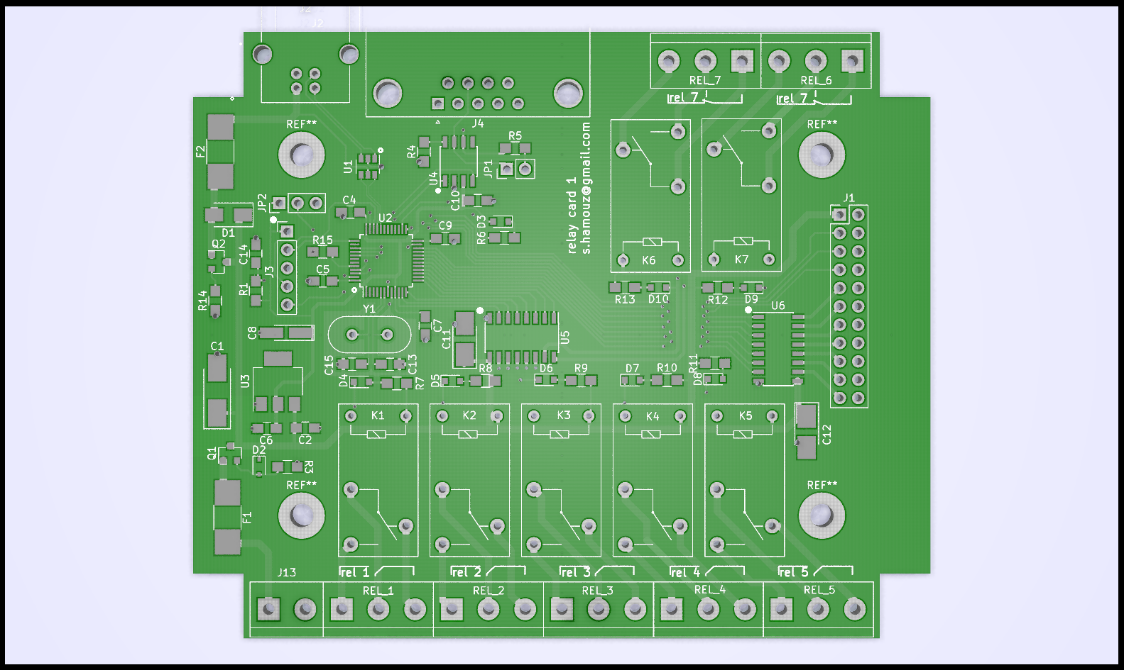
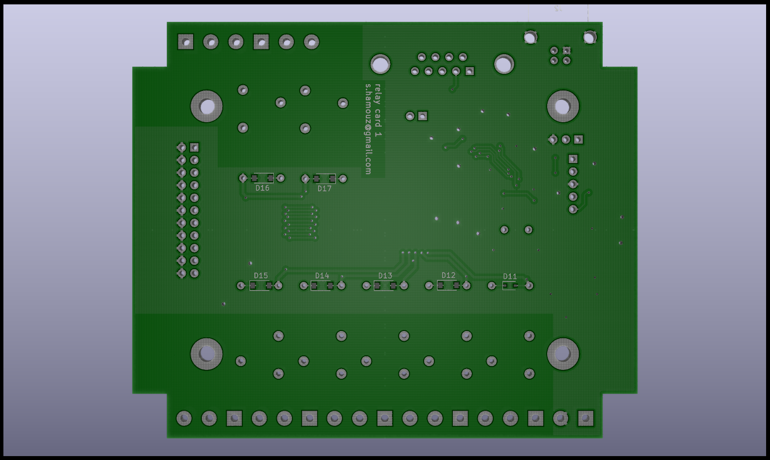
| Qty | Value | Footprint | References |
|---|---|---|---|
| 8 | 570R | Resistors_SMD:R_0805_HandSoldering | R6, R7, R8, R9, R10, R11, R12, R13 |
| 8 | LED | Diodes_SMD:D_0805 | D3, D4, D5, D6, D7, D8, D9, D10 |
| 7 | Conn_01x03 | Connectors_Terminal_Blocks:TerminalBlock_bornier-3_P5.08mm | REL_1, REL_2, REL_3, REL_4, REL_5, REL_6, REL_7 |
| 7 | G5SB-5V | Relays_THT:Relay_SPDT_OMRON-G5Q | K1, K2, K3, K4, K5, K6, K7 |
| 6 | 100n | Capacitors_SMD:C_0805_HandSoldering | C2, C6, C7, C9, C10, C14 |
| 6 | D | Diodes_SMD:D_SOD-123 | D12, D13, D14, D15, D16, D17 |
| 2 | 100n | Capacitors_SMD:C_0805_HandSoldering | C4, C5 |
| 2 | 10uF/16V | Capacitors_Tantalum_SMD:CP_Tantalum_Case-B_EIA-3528-21_Hand | C11, C12 |
| 2 | 22p | Capacitors_SMD:C_0805_HandSoldering | C13, C15 |
| 2 | 33k | Resistors_SMD:R_0805_HandSoldering | R3, R14 |
| 2 | IRLML6402TRPBF | TO_SOT_Packages_SMD:SOT-23 | Q1, Q2 |
| 2 | SD110-16 | Resistors_SMD:R_1812_HandSoldering | F1, F2 |
| 2 | ULN2003A | Housings_SOIC:SOIC-16_3.9x9.9mm_Pitch1.27mm | U5, U6 |
| 1 | 100K | Resistors_SMD:R_0805_HandSoldering | R1 |
| 1 | 100k | Resistors_SMD:R_0805_HandSoldering | R15 |
| 1 | 10k | Resistors_SMD:R_0805_HandSoldering | R4 |
| 1 | 120R | Resistors_SMD:R_0805_HandSoldering | R5 |
| 1 | 2.2uF/6.3V | Capacitors_Tantalum_SMD:CP_Tantalum_Case-A_EIA-3216-18_Hand | C8 |
| 1 | 47uF/16V | Capacitors_Tantalum_SMD:CP_Tantalum_Case-C_EIA-6032-28_Hand | C1 |
| 1 | 5v1 | Diodes_SMD:D_SOD-323 | D2 |
| 1 | 8MHz | Crystals:Crystal_HC49-4H_Vertical | Y1 |
| 1 | AZ1117-3.3 | TO_SOT_Packages_SMD:SOT-223 | U3 |
| 1 | Conn_01x02 | Connectors_Terminal_Blocks:TerminalBlock_bornier-2_P5.08mm | J13 |
| 1 | Conn_01x05 | Pin_Headers:Pin_Header_Straight_1x05_Pitch2.54mm | J3 |
| 1 | Conn_01x09_Male | Connectors_DSub:DSUB-9_Female_Horizontal_Pitch2.77x2.84mm_EdgePinOffset7.70mm_Housed_MountingHolesOffset9.12mm | J4 |
| 1 | Conn_02x11_Odd_Even | Pin_Headers:Pin_Header_Straight_2x11_Pitch2.54mm | J1 |
| 1 | D | Diodes_SMD:D_SOD-323 | D11 |
| 1 | Jumper | Pin_Headers:Pin_Header_Straight_1x02_Pitch2.54mm | JP1 |
| 1 | Jumper_NC_Dual | Pin_Headers:Pin_Header_Straight_1x03_Pitch2.54mm | JP2 |
| 1 | STM32F072C8T6 | Housings_QFP:LQFP-48_7x7mm_Pitch0.5mm | U2 |
| 1 | STPS1L30A | Diodes_SMD:D_SMA | D1 |
| 1 | USBLC6-2SC6 | TO_SOT_Packages_SMD:SOT-23-6 | U1 |
| 1 | USB_B | Connectors:USB_B | J2 |
| 1 | sn65hvd233 | Housings_SOIC:SOIC-8_3.9x4.9mm_Pitch1.27mm | U4 |
The 77 most common of 81 parts.

meteyou/klipper-gcode-buttons
The Klipper Gcode-Buttons offer a unique control and status display solution in 3D printers and automated systems.


hpvdt/typhoon_motherboard
Folder for each of the boards designed for a given project, even if there is only one board for a given project.


It measures 102 × 84 mm and has 2 copper layers, 1.6 mm thick.
81 parts, built around the STM32F072C8T6, SN65HVD233D, ULN2003A and USBLC6-2SC6. The full list of its parts is on this page, with links to each part's symbol and footprint where PCBKit's library has them.
From the chapppy/Board-for-Relay-Card repository on GitHub, at the commit this page was made from: the board is relayCard.kicad_pcb. PCBKit opens the board in the browser, with nothing to install.
Its repository publishes it under the GPL-3.0 licence: you may reuse it on that licence's terms (keep the author's notice, and for a copyleft licence share your changes alike).