2 layers25.4 × 27.4 mm

 cfallin/nixie21
Circuit design and firmware for a GPS-synchronized Nixie-tube clock
Nixie2 is an open-source printed circuit board by cfallin, from the cfallin/nixie2 repository on GitHub. It is a 2-layer board of 68.5 × 181 mm with 51 parts on 122 nets, routed with 748 tracks and 42 vias.
It is built around the ATMEGA8-16PU, 74HC595 and L7805. Its parts include 11 ICs, 8 connectors, 7 resistors, 4 capacitors and 1 crystal. It belongs with the lEDs and displays and radio and wireless boards and the AVR (ATmega, ATtiny) boards of this library.


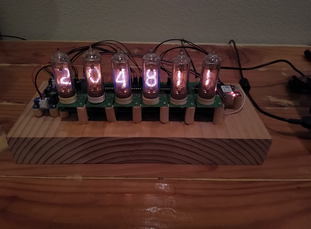
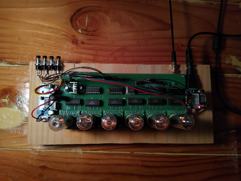
This is a custom-designed (custom circuit design / PCB boards and custom microcontroller firmware) digital clock. It receives the time from a GPS receiver board, adjusts for an user-selectable timezone, and displays the time on "Nixie tubes". A nixie tube is a cold-cathode vacuum tube display technology: it uses high voltage (about 160 volts in this design) applied to an electrode in the shape of a digit in order to display a number in brilliant glowing orange. It really is quite mesmerizing!
This repo contains custom circuit board layouts for the main clock board and a separate adapter sub-board for each Nixie tube. The sub-boards are designed for IN-14 tubes (which can currently be found on eBay or Etsy for ~$20 each), but could be adapted for IN-12, IN-18, or some other size.
The main board contains an AVR ATmega8 microcontroller, a 20MHz crystal, several 74HC595 shift registers to expand the AVR's IO, and six KI155ID1 open-collector high voltage driver chips.
The board interfaces with a separate high-voltage DC-DC power supply, because designing such a supply to be efficient is quite hard and I do not possess the analog black magic skills! I bought this one for $11. You can substitute any suitable source of ~160V DC rated for about 4mA per tube (24mA total, or just under 4 watts).
GPS is also black magic, so I bought a pre-designed GPS receiver module here for $12, and an external active antenna here for $11. The module provides a 1Hz "pulse-per-second" precision output and a 9600bps serial line providing time, position, and satellite lock information using the NMEA protocol. You can substitute any GPS receiver that provides a PPS output and NMEA signal.
The ATmega8 runs firmware that decodes the NMEA to get an initial time (synchronizing whenever a valid NMEA packet with a timestamp is received). It measures the internal crystal oscillator against the PPS and then ticks based on the main CPU clock, calibrated with this ticks-per-PPS value. This allows the clock to receive the time when GPS signal is available, learn how fast or slow its own internal oscillator is running, and then continue to keep time when the GPS signal is lost. Whenever it comes back, time will resynchronize automatically.
There is a simple user interface consisting of four buttons. The leftmost (SW4 on the main board) switches between time mode and set-timezone mode. In the latter, SW2 decrements TZ offset hour and SW1 increments TZ offset hour. (Half-hour or 15 minute timezone offsets are not yet supported; I know these timezones exist, sorry! Happy to take PRs if anyone in such a timezone builds this clock!)
Total cost for the clock, not including the one-time tool purchases I made (e.g. an AVR programmer) or the scrap wood, glue, etc. for the very janky base, and definitely not including my time, was about $230:
I started thinking about building a Nixie clock in 2014, but started working on this design regularly in Nov 2021. It first displayed a GPS-synchronized time on Jan 6, 2022. I'd like to improve the UI a bit (allow a non-GPS locally-set-time mode as well), and definitely improve the casing, but it suits me well enough for now! I finally know what time it is!
| Qty | Value | Footprint | References |
|---|---|---|---|
| 7 | Conn_01x02_Male | Connector_PinHeader_2.54mm:PinHeader_1x02_P2.54mm_Vertical | PWR_IN1, SW1, SW2, SW3, SW4, SW5, SW6 |
| 7 | Conn_01x10_Female | Connector_PinHeader_2.54mm:PinHeader_1x10_P2.54mm_Vertical | J14, NIX1, NIX2, NIX3, NIX4, NIX5, NIX6 |
| 6 | 10k | Resistor_THT:R_Axial_DIN0207_L6.3mm_D2.5mm_P7.62mm_Horizontal | R2, R3, R4, R5, R6, R7 |
| 6 | 74141 | Package_DIP:DIP-16_W7.62mm | U5, U6, U7, U8, U9, U10 |
| 6 | Conn_01x01_Female | Connector_PinHeader_2.54mm:PinHeader_1x01_P2.54mm_Vertical | ANODE1, ANODE2, ANODE3, ANODE4, ANODE5, ANODE6 |
| 3 | 74HC595 | Package_DIP:DIP-16_W7.62mm | U2, U3, U4 |
| 2 | CP | Capacitor_THT:CP_Radial_D10.0mm_P2.50mm | C2, C3 |
| 1 | 100nF | Capacitor_THT:CP_Radial_Tantal_D5.5mm_P2.50mm | C1 |
| 1 | 10k | Resistor_THT:R_Axial_DIN0207_L6.3mm_D2.5mm_P2.54mm_Vertical | R1 |
| 1 | 1uF | Capacitor_THT:CP_Radial_D4.0mm_P1.50mm | C4 |
| 1 | ATmega8-16PU | Package_DIP:DIP-28_W7.62mm | U1 |
| 1 | AVR-ISP-6 | Connector_PinHeader_2.54mm:PinHeader_2x03_P2.54mm_Vertical | J1 |
| 1 | CXO_DIP8 | Oscillator:Oscillator_DIP-8 | X1 |
| 1 | Conn_01x02_Female | Connector_PinHeader_2.54mm:PinHeader_1x02_P2.54mm_Vertical | HV_IN1 |
| 1 | Conn_01x03_Female | Connector_PinHeader_2.54mm:PinHeader_1x03_P2.54mm_Vertical | HVSUP_OUT1 |
| 1 | L7805 | Package_TO_SOT_THT:TO-220-3_Vertical | U11 |
The 46 most common of 51 parts.
It measures 68.5 × 181 mm and has 2 copper layers, 1.6 mm thick.
51 parts, built around the ATMEGA8-16PU, 74HC595 and L7805. The full list of its parts is on this page, with links to each part's symbol and footprint where PCBKit's library has them.
From the cfallin/nixie2 repository on GitHub, at the commit this page was made from: the board is nixie2.kicad_pcb. PCBKit opens the board in the browser, with nothing to install.
Its repository states no licence, so its author keeps all rights: ask cfallin before reusing the design.

jkreucher/eeprom-programmer
A EEPROM Programmer for my z80 stuff. Supported EEPROMS: 28C64, 28C256


ThKattanek/lan64usb
Diese Hard- und Software ermöglicht den Transfer von Programmen vom PC zum Commodore 64 (C64).


ondras12345/vetrnik
Electronics for heating water with power from a 2 kW wind turbine


dineshannayya/riscduino_board
Riscduino PCB Board documentation