Skip to the content
PCBKitNew board
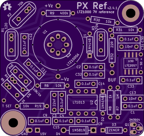
2 layers78.1 × 46.4 mmPxref26, the printed circuit board in 3D

An LTZ1000-based 7V reference (circuit by Andreas)

Size
78.1 × 46.4 mm
Copper layers
2
Thickness
1.6 mm
Parts
72
Nets
31
Pads
158
Tracks, vias
356, 13
Pours
4
Routed
Yes
KiCad
KiCad 3
Created
16 Dec 2017
Updated
30 Aug 2022

Overview

Pxref26 is an open-source printed circuit board by cellularmitosis, from the cellularmitosis/px-ref repository on GitHub, published under the MIT licence. It is a 2-layer board of 78.1 × 46.4 mm with 72 parts on 31 nets, routed with 356 tracks and 13 vias.

It is built around the LT1013DD, LTC2057IMS and LTZ1000ACH, with the JUMPER2 among its other parts. Its parts include 16 capacitors, 11 resistors, 5 connectors, 4 diodes and 3 ICs.

Main components

4

README

README.md

PX Ref

This is an LTZ1000-based 7V reference.

Specifically, this is my board layout of a circuit published by Andreas (of the EEVBlog forum), which in turn is a modification of the 7V reference circuit from the datasheet.

Latest revision

Revision history:

  • v2.4.3
    • Shortened the board very slightly, as the fit in a TEKO 371.16 was just a bit tight.
    • Added two 0.1" holes near LTZ1000 to allow securing a 3D-printed cap.
    • Added more via's in the thermal equalization ring around the LTZ1000.
  • v2.4.2
    • ???
  • v2.4.1
    • Used larger pads on the TO-99 footprint (easier to solder).
    • Moved the input and (buffered) output caps directly onto the board.
  • v2.4
    • The board is slightly smaller and fits within a TEKO 371.16 enclosure.
    • The chassis-ground jumper has been removed (these can now be linked with a small wire).
    • The center pin of the R4/R5 divider has been exposed ("T SET") for off-board manipulation.
    • The LTC2057 shutdown pins have been exposed for off-board control.
  • v2.3
    • The "b" variant has been merged back into a single board design (R4, R5 and R45 are now all on the same board design).
    • The LTC2057 shutdown pins are now left floating.
  • v2.2, v2.2b
    • 2.2 uses a single divider footprint (called R45) for R4 and R5.
    • 2.2b uses separate footprints for R4 and R5.
    • An output buffer was added (LTC2057).
    • Errata:
      • A mistake was made with the LTC2057 shutdown pins which will result in self-heating of a few degrees in the LTC2057. The work-around is to disconnect pins 1 and 8 of the LTC2057.
  • v2.1
    • Added a jumper to optionally link GND to a chassis standoff.
    • Used smaller capacitor footprints.
    • Exposed the star ground as a solderable terminal.
    • Switched D1 from a 1N4001 to a 1N4148.
    • Used smaller footprints for D1 and D2.
    • Errata:
      • Andreas capacitor C15 was accidentally left off of this board design. This cap isn't critical, but a work-around is to bodge a 0.1uF cap across pins 5-6 of the LT1013.
  • v2
    • Switched to a simpler, 2-layer, 50mm x 50mm board design.
  • v1
    • First design. 4-layer with via stitching for a mild EMI shielding effect.
    • This board was never ordered and tested.

Schematic

Andreas' original schematic: png

My adapted version of Andreas' schematic: pdf

Purchasing

You can order a copy of this board from OSHPark: link

Discussion

My posts to the EEVBlog forum about this design: link link

The naming of this board was inspired by other LTZ1000 references: KX, FX, MX, CX, QX

See also:

Parts

72
QtyValueFootprintReferences
110.1uFBOXCAP_01_03_02_059AC1, C2, C4, C8, C11, C12, C14, C15, C30, C32, C33
10Val**1pin_032_058H***, H***, H***, H***, H***, H***, H***, H***, H***, H***
9Val**Via_016H***, H***, H***, H***, H***, H***, H***, H***, H***
7JUMPER2SIL-2JP3, JP5, JP50, JP51, JP52, JP54, JP56
410kR_AXIAL_0W25_059A_PLR6, R19, R30, R31
3CONN_1X11pin_040_069P2, P3, P5
3Val**hole_M3H***, H***, H***
210nFBOXCAP_01_03_02_059AC13, C31
21N4148DIODE_SS_059A_03_PLD1, D2
21uFBOXCAP_02_03_03_059AC34, C40
2CONN_2X1ferrite_core_20x12_PLP1, P6
110uHR_AXIAL_0W25_059A_PLL40
1120R_BOX_HERMETIC_WW_AXIAL_07_PLR1
11MR_AXIAL_0W25_059A_PLR7
11N5819DIODE_1A_069A_04_PLD4
11kR_AXIAL_0W25_059A_PLR8
122RR_AXIAL_0W25_059A_PLR32
122nFBOXCAP_01_03_02_059AC3
12N3904TO-92_Q_EBC_059Bo_PLQ1
14.7RR_AXIAL_0W25_059A_PLR40
1400kR_AXIAL_0W25_059A_PLR9
1HOLEhole_M3H1
1LT1013DIP8_059A_PLU2
1LTC2057SO-8U30
1LTZ1000ATO-99_PLU1
1OHMTEK_132077DIP16_PLR50
1OSHW-logo_silkscreen-front_4mmOSHW-logo_silkscreen-front_4mmG***
1ZENERDIODE_SS_059A_03_PLD3

Questions

How big is the Pxref26 PCB?

It measures 78.1 × 46.4 mm and has 2 copper layers, 1.6 mm thick.

What parts does the Pxref26 use?

72 parts, built around the LT1013DD, LTC2057IMS, LTZ1000ACH and JUMPER2. The full list of its parts is on this page, with links to each part's symbol and footprint where PCBKit's library has them.

Where can I download the Pxref26 KiCad files?

From the cellularmitosis/px-ref repository on GitHub, at the commit this page was made from: the board is kicad/pxref26.kicad_pcb. PCBKit opens the board in the browser, with nothing to install.

Can I use the Pxref26 design in my own project?

Its repository publishes it under the MIT licence: you may reuse it on that licence's terms (keep the author's notice, and for a copyleft licence share your changes alike).

More from cellularmitosis/px-ref

2
  • 2 layers48.9 × 45.7 mmPxref24, the printed circuit board in 3D

    Pxref24

    cellularmitosis/px-ref

    An LTZ1000-based 7V reference (circuit by Andreas)

    78 parts11MIT
  • 2 layers78.1 × 46.4 mmPxref25, the printed circuit board in 3D

    Pxref25

    cellularmitosis/px-ref

    An LTZ1000-based 7V reference (circuit by Andreas)

    71 parts11MIT

Similar boards

  • 2 layers49.5 × 42.5 mmHp ref, the printed circuit board in 3D

    Hp ref

    cellularmitosis/hp-03458-66509-clone

    A clone of the LTZ1000 reference board from the HP 3458A 8.5-digit multimeter

    46 parts12MIT
  • 2 layers79.9 × 49.9 mmDr frank ltz1000, the printed circuit board in 3D

    Dr frank ltz1000

    cellularmitosis/dr-frank-ltz1000

    Dr. Frank's LTZ1000 reference

    57 parts9
  • 2 layers79.9 × 50 mmLtz1000, the printed circuit board in 3D

    Ltz1000

    opendcm/opendcm

    Open DC multimeter

    41 parts12
  • 2 layers50.2 × 44.5 mmA9ref, the printed circuit board in 3D

    A9ref

    sgenomics/pcbs

    There are my personal PCBs... contact me for licensing information.

    25 parts2
  • 2 layers34.5 × 56 mmMu ltz, the printed circuit board in 3D

    Mu ltz

    marcoreps/LTZmu

    Low cost 10V transfer standard

    46 parts20
  • 2 layers50 × 100 mmEv LTZ, the printed circuit board in 3D

    Ev LTZ

    evetere/eV-LTZ1000

    LTZ1000 reference schematic and board (kicad)

    38 parts3
  • 2 layers354.3 × 253 mmDCMGv2wBUFFERS, the printed circuit board in 3D

    DCMGv2wBUFFERS

    Jordan87M/DCMG

    kicad files for a DC microgrid hardware model

    548 parts1
  • 2 layers50 × 40 mmLTZ1000 Board, the printed circuit board in 3D

    LTZ1000 Board

    NNNILabs/LTZ1000-Reference-Board

    Bare-bones LTZ1000 carrier PCB

    21 parts1