
2 layers78.1 × 46.4 mm

 cellularmitosis/px-ref11
An LTZ1000-based 7V reference (circuit by Andreas)
Pxref24 is an open-source printed circuit board by cellularmitosis, from the cellularmitosis/px-ref repository on GitHub, published under the MIT licence. It is a 2-layer board of 48.9 × 45.7 mm with 78 parts on 22 nets, routed with 259 tracks and 9 vias.
It is built around the LT1013DD, LTC2057IMS and LTZ1000ACH. Its parts include 15 capacitors, 14 resistors, 5 connectors, 4 diodes and 3 ICs.


This is an LTZ1000-based 7V reference.
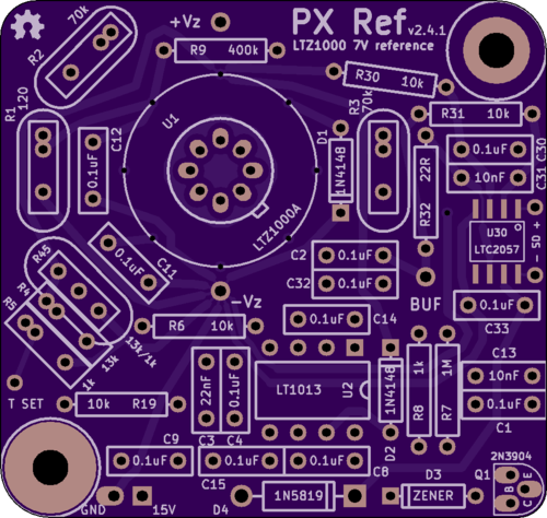
Specifically, this is my board layout of a circuit published by Andreas (of the EEVBlog forum), which in turn is a modification of the 7V reference circuit from the datasheet.
Andreas' original schematic: png
My adapted version of Andreas' schematic: pdf
You can order a copy of this board from OSHPark: link
My posts to the EEVBlog forum about this design: link link
The naming of this board was inspired by other LTZ1000 references: KX, FX, MX, CX, QX
See also:
| Qty | Value | Footprint | References |
|---|---|---|---|
| 28 | Val** | Via_016 | H***, H***, H***, H***, H***, H***, H***, H***, H***, H***, H***, H***, H***, H***, H***, H*** +12 |
| 12 | 0.1uF | BOXCAP_01_03_02_059A | C1, C2, C4, C8, C9, C11, C12, C14, C15, C30, C32, C33 |
| 5 | CONN_1X1 | 1pin_040_069 | P1, P2, P3, P4, P5 |
| 5 | Val** | 1pin_032_058 | H***, H***, H***, H***, H*** |
| 4 | 10k | R_AXIAL_0W25_059A_PL | R6, R19, R30, R31 |
| 2 | 10nF | BOXCAP_01_03_02_059A | C13, C31 |
| 2 | 1N4148 | DIODE_SS_059A_PL | D1, D2 |
| 2 | 70k | R_BOX_HERMETIC_PL | R2, R3 |
| 1 | 120 | R_BOX_HERMETIC_PL | R1 |
| 1 | 13k | R_BOX_PL | R4 |
| 1 | 13k/1k | R_BOX_DIVIDER_PL | R45 |
| 1 | 1M | R_AXIAL_0W25_059A_PL | R7 |
| 1 | 1N5819 | DIODE_1A_069A_PL | D4 |
| 1 | 1k | R_AXIAL_0W25_059A_PL | R8 |
| 1 | 1k | R_BOX_PL | R5 |
| 1 | 22R | R_AXIAL_0W25_059A_PL | R32 |
| 1 | 22nF | BOXCAP_01_03_02_059A | C3 |
| 1 | 2N3904 | TO-92_Q_EBC_059Bo_PL | Q1 |
| 1 | 400k | R_AXIAL_0W25_059A_PL | R9 |
| 1 | HOLE | hole_M3 | H1 |
| 1 | LT1013 | DIP8_059A_PL | U2 |
| 1 | LTC2057 | SO-8 | U30 |
| 1 | LTZ1000A | TO-99_PL | U1 |
| 1 | OSHW-logo_silkscreen-front_3mm | OSHW-logo_silkscreen-front_3mm | G*** |
| 1 | Val** | hole_M3 | H*** |
| 1 | ZENER | DIODE_SS_059A_PL | D3 |
It measures 48.9 × 45.7 mm and has 2 copper layers, 1.6 mm thick.
78 parts, built around the LT1013DD, LTC2057IMS and LTZ1000ACH. The full list of its parts is on this page, with links to each part's symbol and footprint where PCBKit's library has them.
From the cellularmitosis/px-ref repository on GitHub, at the commit this page was made from: the board is kicad/pxref24.kicad_pcb. PCBKit opens the board in the browser, with nothing to install.
Its repository publishes it under the MIT licence: you may reuse it on that licence's terms (keep the author's notice, and for a copyleft licence share your changes alike).


cellularmitosis/hp-03458-66509-clone
A clone of the LTZ1000 reference board from the HP 3458A 8.5-digit multimeter


