4 layers76.7 × 45.3 mm
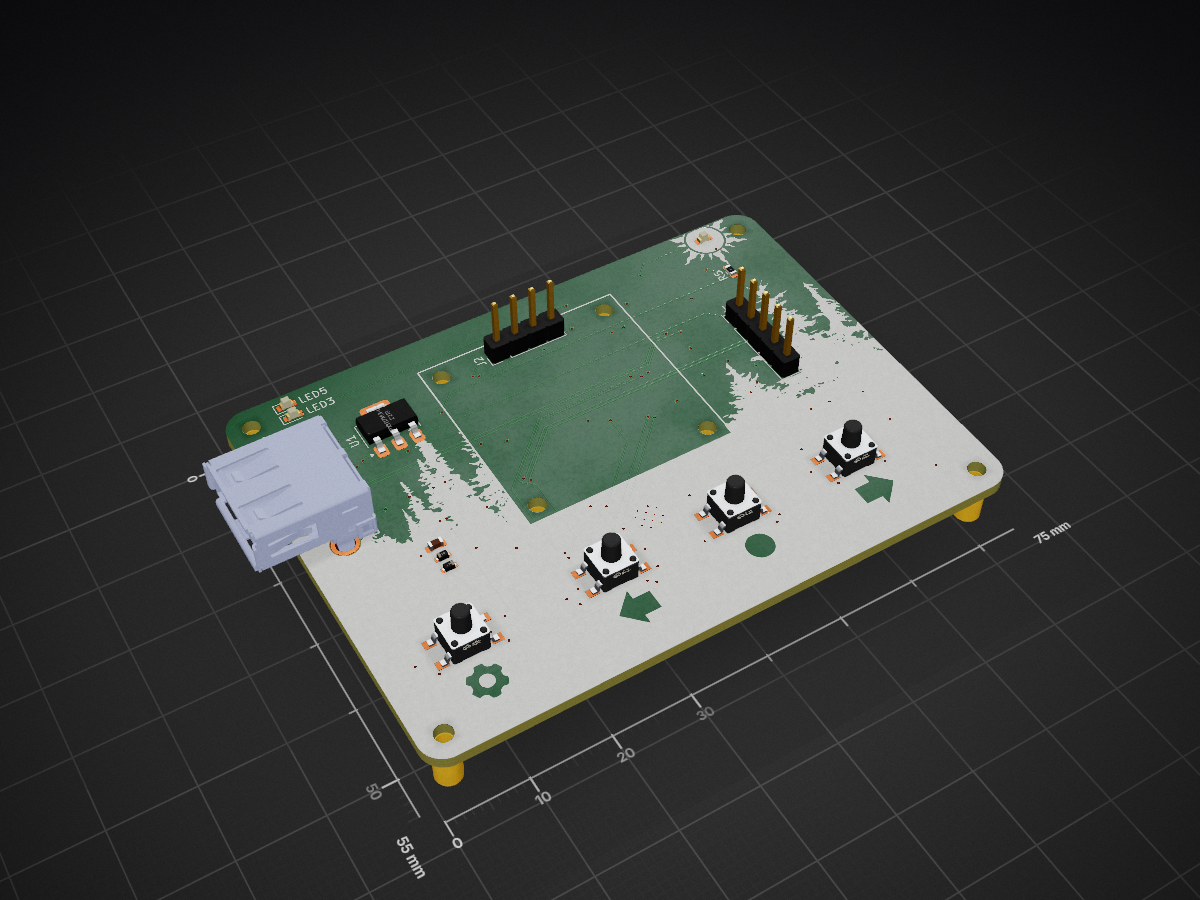
 cedarhacks/HIDMorph4
Hardware/Firmware of HIDMorph, a lua configurable HID translation/generation device
HIDMorph is an open-source printed circuit board by cedarhacks, from the cedarhacks/HIDMorph repository on GitHub. It is a 4-layer board of 75 × 55 mm with 50 parts on 91 nets, routed with 432 tracks and 83 vias.
It is built around the RP2040, ESP32-S3-WROOM-1-N8R8 and W25Q128JVEIQ, with the SPX1117M3-L-3-3/TR among its other parts. Its parts include 14 capacitors, 7 diodes, 6 resistors, 5 ICs and 5 switches. It belongs with the ESP32 and RP2040 boards of this library.


HIDMorph is a programmable USB HID host/device translator built on a dual-MCU architecture (ESP32-S3 + RP2040).
It enables real-time translation, remapping, and transformation of USB HID inputs (keyboards, mice, controllers) without requiring firmware recompilation.
The system is designed as an embedded product, combining real-time firmware, USB protocol handling, and custom hardware.
HIDMorph uses a dual-MCU design to cleanly separate USB responsibilities:
RP2040
ESP32-S3
Communication between MCUs is handled over a dedicated internal interface designed for low latency and robustness.
(Architecture diagram coming soon)
(Schematics, PCB renders, and photos will be added as the design stabilizes)
HIDMorph is under active development.
Completed:
In progress:
| Qty | Value | Footprint | References |
|---|---|---|---|
| 8 | , , , , , , , | ||
| 4 | ESD | Diode_SMD:D_SOD-523 | D1, D2, D3, D4 |
| 3 | 2.2uf | Capacitor_SMD:C_0603_1608Metric | C5, C10, C13 |
| 3 | 47uF | Capacitor_SMD:C_0603_1608Metric | C1, C3, C7 |
| 3 | 500 | Resistor_SMD:R_0603_1608Metric | R3, R6, R8 |
| 2 | 0.1uf | Capacitor_SMD:C_0603_1608Metric | C4, C9 |
| 2 | 100nf | Capacitor_SMD:C_0603_1608Metric | C6, C14 |
| 2 | 15 pF | Capacitor_SMD:C_0603_1608Metric | C11, C12 |
| 2 | 1k | Resistor_SMD:R_0603_1608Metric | R2, R5 |
| 2 | LED RP5 | LED_SMD:LED_0603_1608Metric | LED3, LED5 |
| 2 | W25Q128JVE | Package_SON:WSON-8-1EP_8x6mm_P1.27mm_EP3.4x4.3mm | U2, U5 |
| 1 | 10k | Resistor_SMD:R_0603_1608Metric | R1 |
| 1 | 12MHZ | Crystal:Crystal_SMD_3225-4Pin_3.2x2.5mm | Y1 |
| 1 | 1uf | Capacitor_SMD:C_0603_1608Metric | C2 |
| 1 | 22uf | Capacitor_SMD:C_0603_1608Metric | C8 |
| 1 | ESP32-S3-WROOM-1-N8R8 | RF_Module:ESP32-S3-WROOM-1 | U3 |
| 1 | ESP_B1 | generated_lscs:SW-SMD_4P-L4.5-W4.5-P3.00-LS6.8 | S3 |
| 1 | ESP_B2 | generated_lscs:SW-SMD_4P-L4.5-W4.5-P3.00-LS6.8 | S4 |
| 1 | ESP_B3 | generated_lscs:SW-SMD_4P-L4.5-W4.5-P3.00-LS6.8 | S5 |
| 1 | ESP_B4_prog | generated_lscs:SW-SMD_4P-L4.5-W4.5-P3.00-LS6.8 | S6 |
| 1 | I2C Display | Connector_PinHeader_2.54mm:PinHeader_1x04_P2.54mm_Vertical | J2 |
| 1 | LED 33V | LED_SMD:LED_0603_1608Metric | LED1 |
| 1 | PogoPIN | cedarhacks:pogo_pin_2.54mm | J5 |
| 1 | Programming Pins | footprints:SW_DIP_219-4 | SW1 |
| 1 | RP2040 | footprints:rp2040 | U4 |
| 1 | SPX1117M3-L-3-3/TR | Package_TO_SOT_SMD:SOT-223 | U1 |
| 1 | USB_IN | footprints:USBA_Female | J3 |
| 1 | USB_OUT | Connector_PinHeader_2.54mm:PinHeader_1x05_P2.54mm_Vertical | J4 |
It measures 75 × 55 mm and has 4 copper layers, 1.6 mm thick.
50 parts, built around the RP2040, ESP32-S3-WROOM-1-N8R8, W25Q128JVEIQ and SPX1117M3-L-3-3/TR. The full list of its parts is on this page, with links to each part's symbol and footprint where PCBKit's library has them.
From the cedarhacks/HIDMorph repository on GitHub, at the commit this page was made from: the board is electrical/HIDMorph/HIDMorph.kicad_pcb and its schematic W25Q128JV_breakout/W25Q128JV_breakout/W25Q128JV_breakout.kicad_sch. PCBKit opens the board in the browser, with nothing to install.
Its repository states no licence, so its author keeps all rights: ask cedarhacks before reusing the design.

Boardoza/Boardoza_SPX1117-3V3_LDO_Regulator_Breakout_Board
Boardoza SPX1117-3V3 Breakout Board provides a stable and low-noise 3.3V regulated power supply with up to 800mA output current.


joshitha-c/microphone
A compact USB digital microphone development board built around the Raspberry Pi RP2040 microcontroller and the STMicroelectronics MP34DT05TR-A digital MEMS microphone.