4 layers68.6 × 53.3 mm

 red-scorp/RP2040-DebugProbe8
RP2040-based debug probe board
RP2040-DebugProbe is an open-source printed circuit board by red-scorp, from the red-scorp/RP2040-DebugProbe repository on GitHub. It is a 4-layer board of 50.8 × 25.4 mm with 66 parts on 79 nets, routed with 563 tracks and 138 vias.
It is built around the RP2040, 74AUP1T17GWH and W25Q128JVEIQ, with the W25Q128JVSIQ, AMS1117-3.3 and PRTR5V0U2X among its other parts. Its parts include 23 resistors, 21 capacitors, 7 diodes, 6 ICs and 6 connectors. It belongs with the sensors and measurement and interfaces and adapters boards and the RP2040 boards of this library.


____________  _____  _____    ___ _____
| ___ \ ___ \/ __  \|  _  |  /   |  _  |
| |_/ / |_/ /`' / /'| |/' | / /| | |/' |
|    /|  __/   / /  |  /| |/ /_| |  /| |
| |\ \| |    ./ /___\ |_/ /\___  \ |_/ /
\_| \_\_|    \_____/ \___/     |_/\___/
______     _                ______          _
|  _  \   | |               | ___ \        | |
| | | |___| |__  _   _  __ _| |_/ / __ ___ | |__   ___
| | | / _ \ '_ \| | | |/ _` |  __/ '__/ _ \| '_ \ / _ \
| |/ /  __/ |_) | |_| | (_| | |  | | | (_) | |_) |  __/
|___/ \___|_.__/ \__,_|\__, \_|  |_|  \___/|_.__/ \___|
                        __/ |
|___/ The RP2040-DebugProbe project aims to re-imagine Raspberry Pi Debug Probe.
The RP2040-DebugProbe board is a 4-layer design intended to accommodate the popular Raspberry Pi RP2040 MCU with all required component to function identically to Raspberry Pi Debug Probe.
This board features target JTAG connector and PC host USB Type-C connector. It also has a SWD connector and UART connector for the main MCU debugging. The board is pin-compatible with Raspberry Pi Debug Probe and can be used with the same picoprobe SW.
Preview:
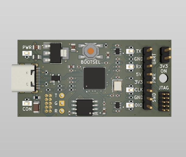
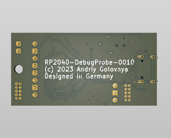
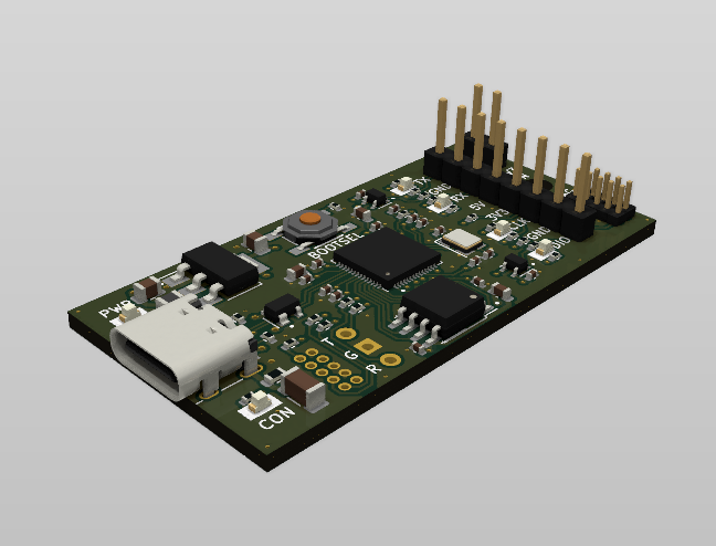
You can view the Schematics in PDF format for detailed information.
STEP 3D file is available with pins.
Features:
CAM files, as well as the BOM and CPL files for JLCPCB, are available.
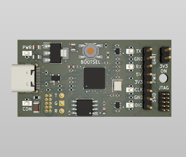
Initial release for testing purposes.
Your contributions as code, resources, or finances are welcome! Please contact me directly via email at andriy.golovnya@gmail.com or through my GitHub profile.
If you'd like to make a financial contribution, you can donate via PayPal or Ko-Fi. Your support is greatly appreciated.
Thanks in advance!
| Qty | Value | Footprint | References |
|---|---|---|---|
| 13 | 100nF | Capacitor_SMD:C_0402_1005Metric | C2, C3, C4, C6, C7, C8, C9, C10, C11, C12, C13, C17, C18 |
| 12 | 100R | Resistor_SMD:R_0402_1005Metric | R9, R13, R14, R15, R16, R17, R18, R19, R20, R21, R22, R23 |
| 7 | 1k | Resistor_SMD:R_0402_1005Metric | R1, R2, R3, R4, R5, R6, R7 |
| 3 | 2.2uF | Capacitor_SMD:C_0603_1608Metric | C1, C5, C16 |
| 2 | 10uF | Capacitor_SMD:C_0805_2012Metric | C14, C15 |
| 2 | 12pF | Capacitor_SMD:C_0402_1005Metric | C19, C20 |
| 2 | 5k1 | Resistor_SMD:R_0402_1005Metric | R10, R11 |
| 2 | 74AUP1T17 | Package_TO_SOT_SMD:SOT-353_SC-70-5 | U3, U6 |
| 2 | GREEN | LED_SMD:LED_0603_1608Metric | D1, D6 |
| 2 | RED | LED_SMD:LED_0603_1608Metric | D2, D5 |
| 2 | YELLOW | LED_SMD:LED_0603_1608Metric | D4, D7 |
| 1 | 100@100MHz | Inductor_SMD:L_0805_2012Metric | FB2 |
| 1 | 10k | Resistor_SMD:R_0402_1005Metric | R8 |
| 1 | 12MHz | Crystal:Crystal_SMD_3225-4Pin_3.2x2.5mm | Y1 |
| 1 | 1M | Resistor_SMD:R_0603_1608Metric | R12 |
| 1 | 4.7nF 1kV | Capacitor_SMD:C_1206_3216Metric | C21 |
| 1 | AMS1117-3.3 | Package_TO_SOT_SMD:SOT-223-3_TabPin2 | U5 |
| 1 | BOOTSEL | PCM_4ms_Switch:Button_Tact_Sqkg | SW1 |
| 1 | CONN_3V3_JUMPER | Connector_PinHeader_2.54mm:PinHeader_1x02_P2.54mm_Vertical | J4 |
| 1 | CONN_DBG_COMB | Connector_PinHeader_2.54mm:PinHeader_1x08_P2.54mm_Vertical | J3 |
| 1 | CONN_DBG_JTAG | Connector_PinHeader_1.27mm:PinHeader_2x05_P1.27mm_Vertical | J7 |
| 1 | CONN_MCU_JTAG | Connector_PinHeader_1.27mm:PinHeader_2x05_P1.27mm_Vertical | J1 |
| 1 | CONN_MCU_UART | Connector_PinHeader_2.54mm:PinHeader_1x03_P2.54mm_Vertical | J2 |
| 1 | CONN_USB | Connector_USB:USB_C_Receptacle_HRO_TYPE-C-31-M-12 | J10 |
| 1 | PRTR5V0U2X | Package_TO_SOT_SMD:SOT-143 | D3 |
| 1 | RP2040 | Package_DFN_QFN:QFN-56-1EP_7x7mm_P0.4mm_EP3.2x3.2mm | U2 |
| 1 | W25Q128JVEIQ | Package_SON:WSON-8-1EP_6x5mm_P1.27mm_EP3.4x4.3mm | U4 |
| 1 | W25Q128JVS | Package_SO:SOIC-8_5.23x5.23mm_P1.27mm | U1 |
It measures 50.8 × 25.4 mm and has 4 copper layers, 1.61 mm thick.
66 parts, built around the RP2040, 74AUP1T17GWH, W25Q128JVEIQ and W25Q128JVSIQ. The full list of its parts is on this page, with links to each part's symbol and footprint where PCBKit's library has them.
From the red-scorp/RP2040-DebugProbe repository on GitHub, at the commit this page was made from: the board is RP2040-DebugProbe.kicad_pcb and its schematic RP2040-DebugProbe.kicad_sch. PCBKit opens the board in the browser, with nothing to install.
Its repository states no licence, so its author keeps all rights: ask red-scorp before reusing the design.


RivasMario/SKYWAY-96
Mechanical Keyboard PCB and Plate powered by QMK for a 96% board


shanteacontrols/OpenDeck
A platform for building interactive control and sensing devices using MIDI and OSC built with Zephyr RTOS.

ph-design/PH60-SC
A printable low-profile 60% wireless mechanical keyboard kit powered by ZMK firmware.

dededecline/Serendipity
Serendipity keyboard designed by @ojthetiny and me.