Skip to the content
PCBKitNew board
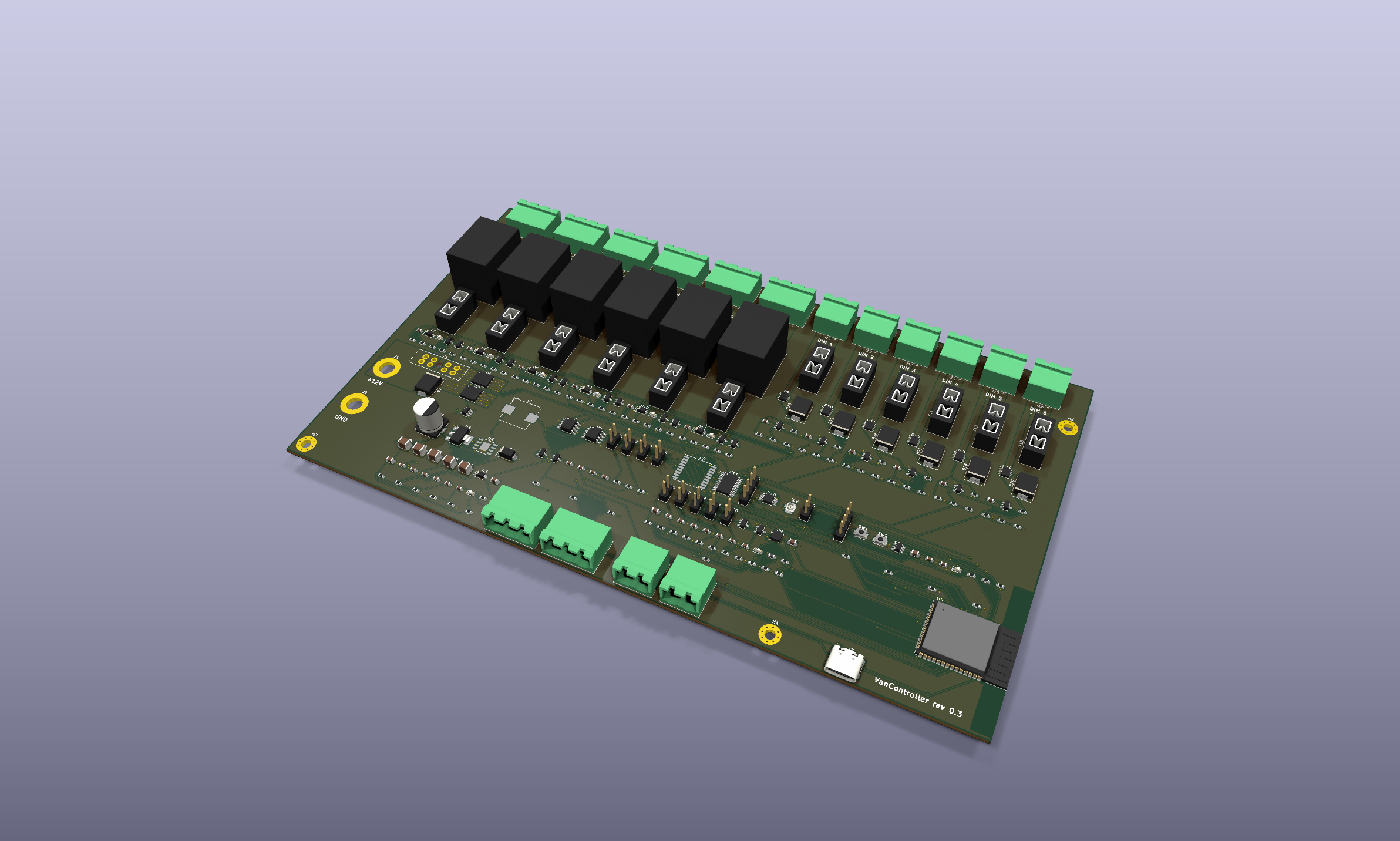
4 layers230 × 135 mmVancontroller, the printed circuit board in 3D

VanController: ESP32-S3 12 V campervan controller board (6 fused relays, 6 PWM dimmers, CAN, RS485, GPS) - KiCad 10 design, manufacturing files and enclosure. Free for non-commercial use.

Size
230 × 135 mm
Copper layers
4
Thickness
1.6 mm
Parts
259
Nets
173
Pads
921
Tracks, vias
2,016, 425
Pours
13
Routed
Yes
KiCad
KiCad 10.0 (file 20260206)
Created
7 Oct 2026
Updated
14 Oct 2026

Overview

Vancontroller is an open-source printed circuit board by Camperlux, from the Camperlux/vancontroller repository on GitHub. It is a 4-layer board of 230 × 135 mm with 259 parts on 173 nets, routed with 2,016 tracks and 425 vias.

It is built around the ESP32-S3-WROOM-1-N16, THVD1450D and TJA1051T/3, with the ADS1115IDGS, TPS54360DDA and AMS1117-3.3 among its other parts. Its parts include 87 resistors, 42 capacitors, 39 diodes, 19 connectors and 14 transistors. It belongs with the interfaces and adapters and radio and wireless boards and the ESP32 boards of this library.

Main components

12

README

README.md

VanController

A 12 V campervan controller board: ESP32-S3 with 6 fused relays, 6 fused PWM dimmers, CAN, RS485, GPS, an accelerometer and 2 water-level inputs, plus a 3D-printable enclosure. Designed in KiCad 10.

VanController rev 0.3, populated

Revision0.3a
StatusDesign complete (ERC and DRC clean). Prototype order with PCBWay under engineering review since 2026-10-06; see docs/ORDER_LOG.md. Not yet verified on hardware.
Board230 × 135 mm, 4 layers (In1 = GND plane, In2 = +12 V plane), 1.6 mm, 1 oz copper, ENIG
Enclosure251 × 142 × 35 mm two-part print with mounting ears (enclosure/)

Features

  • Power: 12 V input on M5 studs. 30 A ATO main fuse, bidirectional load-dump TVS, LM74700-Q1 ideal-diode reverse-polarity protection with 2 × CSD18540Q5B, TPS54360 buck to 5 V, AMS1117 to 3.3 V. Input voltage sensing.
  • 6 relay outputs: Omron G5LE 10 A, each with its own mini blade fuse, COM/NO/NC terminals (COM = fused +12 V by default), indicator LED and fuse-blown sensing. Any channel converts to a dry contact by removing its fuse and cutting a solder jumper (DESIGN_SPEC.md §4).
  • 6 dimmer outputs: 60 V logic-level MOSFETs (low side, PWM), 5 A mini blade fuse each, freewheel diode, fuse-blown sensing.
  • Comms: CAN (TJA1051T/3) and RS485 (THVD1450), with jumper-selectable termination and fail-safe bias.
  • Sensors: u-blox MAX-M10S GPS (u.FL active antenna), LIS3DH accelerometer, ADS1115 16-bit ADC with 2 water-level inputs (each jumper-selectable for resistive, 4-20 mA or 0-5 V senders).
  • MCU: ESP32-S3-WROOM-1-N16 with native USB-C, BOOT/RESET buttons and a UART debug header. Wi-Fi/BLE antenna at the board edge, with no copper under it.
  • Terminals: all 12 outputs along one edge on Phoenix MSTBA 5.08 mm pluggable headers.

Documents

DocumentContents
DESIGN_SPEC.mdDesign decisions, GPIO map, I2C addresses, terminal pinouts, PCB notes, open design checks, firmware notes
docs/ORDER_LOG.mdManufacturing record: PCBWay quote and cart items, decisions (1 oz copper, ENIG, self-fitted through-hole parts), engineering Q&A, open items
docs/VanController_schematic.pdfFull schematic (19 pages)
docs/VanController_assembly_top.pdfTop-side assembly drawing with reference designators
docs/Board and placement images, 3D renders

Repository layout

PathContents
VanController.kicad_pro, *.kicad_sch, VanController.kicad_pcbKiCad 10 project. Hierarchical schematic: root → Power, MCU, Relays (6 × relay_channel), Dimmers (6 × dimmer_channel), Comms, Sensors
fab/Gerbers + drill (gerbers/, VanController_gerbers.zip), BOM, pick-and-place, board STEP model
manufacturing/VanController_rev0.3_PCBWay/The order package sent to PCBWay: Gerbers, BOM with manufacturer part numbers (xlsx), centroid file, order notes, drawings, 3D model, optional enclosure print files
enclosure/Fusion 360 enclosure script, print-ready STLs, assembly STEP with the PCB (run the script to recreate the Fusion design)
tools/Python scripts that generated and finish the project (see below)

Ordering and building

  1. Order: upload the files from manufacturing/VanController_rev0.3_PCBWay/ (read 00_READ_ME_ORDER_NOTES.txt), or rebuild the package with python tools/make_order_package.py. Settings used: 4 layers, 1.6 mm, 1 oz copper (2 oz is not manufacturable with this design's 0.15 mm fine-pitch spacing), ENIG, SMD-only assembly.
  2. Through-hole parts are fitted by hand: relays K1-K6, terminal headers, fuse holders F1-F13 and pin headers (47 per board). The relay, F1 and output terminal joints sit on large copper areas, so use a 60-80 W iron.
  3. Not fitted by the assembler: blade fuses (size each to its load), jumper shunts (choose per DESIGN_SPEC.md §4) and the M5 stud bolts for J1/J2.
  4. Enclosure: print enclosure/VanController_base.stl and VanController_lid.stl in PETG or ASA (not PLA). Hardware: 8 × M3 heat-set inserts, 4 × M3×8 (lid), 4 × M3×6 (PCB), 2 × M16 cable glands, 1 × SMA bulkhead to u.FL pigtail.
  5. First power-up: use a current-limited bench supply, check +5 V and +3V3, then fit fuses one output at a time. See DESIGN_SPEC.md §7 for the thermal and load checks.

How the design was generated

The schematic and board were generated by scripts, then routed and hand-fixed. From now on, edit the design in KiCad. The board contains hand fixes (around U9) that no script reproduces, so do not regenerate it.

ScriptPurposeOverwrites
tools/gen_schematic.pyBuilds every schematic sheet from the circuit tables in the scriptall .kicad_sch
tools/gen_pcb.py (KiCad Python)Builds the board from the netlist: footprints, placement, high-current copper, planes, plane fan-out viasVanController.kicad_pcb
tools/netclasses.pyWrites net classes and design rules into .kicad_pronet settings
Freerouting 1.9.0Autoroutes the exported DSN: java -jar freerouting-1.9.0.jar -de vc.dsn -do vc.ses -mp 40 -mt 1—
tools/finish_pcb.py (KiCad Python)Imports routes, adds outer GND pours, fills zones, tidies silkscreenthe board given
tools/fix_pcb.py (KiCad Python)Fixes via drills, removes dangling router tails, refills zonesthe board given
tools/patch_pcb.py (KiCad Python)Hand fixes: MOSFET gate link on B.Cu, vias for stranded plane padsthe board given
tools/patch_dry_contact.py + tools/strip_sj_courtyard.pyRev 0.3a: adds the SJ dry-contact jumpers to the routed boardVanController.kicad_pcb
tools/make_fab.pyGerbers, drill, BOM, pick-and-place, STEP, PDFsfab/, docs/
tools/make_order_package.pyBuilds the PCBWay order package (xlsx BOM with MPNs, board-origin centroid, notes)manufacturing/
enclosure/VanControllerEnclosure/VanControllerEnclosure.pyFusion 360 script: builds base + lid, imports the PCB, exports STL/STEP/f3d into the enclosure/ folder next to itenclosure/ outputs

Tool notes:

  • KiCad Python is C:\Program Files\KiCad\10.0\bin\python.exe.
  • Freerouting is not in the repo: download freerouting-1.9.0.jar from the Freerouting releases into tools/freerouting/. Use 1.9.0 with -mt 1: version 2.x ignores the pass limit from the command line, and multithreaded optimisation creates clearance errors.
  • Before exporting the DSN, set the inner layers to power-plane type (gen_pcb.py does this), or Freerouting routes signals on them and splits the planes.

Lessons learned (rev 0.3)

  • Fan out SMD pads on plane nets (stub + via) before autorouting: unrouted connections fell from 499 to 5.
  • Check that autorouted tracks don't cut high-current copper areas: an early route split one input MOSFET's sources off the input.
  • 2 oz outer copper needs ≥ 6.5-8 mil spacing. Fine-pitch ICs at 0.15 mm force 1 oz.
  • PCBWay wants ≥ 0.19 mm between pads for solder-mask dams. Below that, the mask is opened across the IC.
  • KiCad Python: PCB_VIA.GetWidth() without a layer argument raises an invisible assert dialog that hangs the script. Use GetWidth(pcbnew.F_Cu).

Revision history

RevDateChanges
0.12026-10-05Spec, GPIO map, hierarchical sheet skeleton
0.22026-10-05Full schematic (ERC clean); first 169 × 135 mm placement
0.32026-10-05/06230 × 135 mm rectangular layout with all outputs on one edge; plane fan-out; routed (DRC clean); TCA9535 address changed to 0x21; enclosure; PCBWay order package and order submitted
0.3a2026-10-14Dry-contact option: solder jumpers SJ1-SJ6 isolate the fuse-sense resistor from relay COM (tools/patch_dry_contact.py). Copper-only change: Gerbers updated, BOM and placement unchanged

Licence

Copyright (c) 2026 Camperlux. Free for non-commercial use. The hardware design, manufacturing files and documentation are under CC BY-NC-SA 4.0, and the scripts are under the PolyForm Noncommercial License 1.0.0. Commercial use, including selling boards, kits or products based on this design, needs a licence from Camperlux. See NOTICE.md for details and third-party parts.

Parts

259
QtyValueFootprintReferences
2110kResistor_SMD:R_0603_1608MetricR6, R39, R40, R41, R42, R43, R44, R63, R64, R65, R66, R67, R68, R71, R76, R77 +5
14BAT54SPackage_TO_SOT_SMD:SOT-23D18, D19, D20, D21, D22, D23, D30, D31, D32, D33, D34, D35, D38, D39
13100nFCapacitor_SMD:C_0603_1608MetricC1, C7, C14, C16, C30, C31, C33, C35, C38, C39, C40, C41, C42
1310nFCapacitor_SMD:C_0603_1608MetricC18, C19, C20, C21, C22, C23, C24, C25, C26, C27, C28, C29, C36
12100kResistor_SMD:R_0603_1608MetricR21, R22, R23, R24, R25, R26, R51, R52, R53, R54, R55, R56
1233kResistor_SMD:R_0603_1608MetricR33, R34, R35, R36, R37, R38, R57, R58, R59, R60, R61, R62
6100Resistor_SMD:R_0603_1608MetricR15, R16, R17, R18, R19, R20
610A miniFuse:Fuseholder_Blade_Mini_Keystone_3568F2, F3, F4, F5, F6, F7
61N4148WDiode_SMD:D_SOD-123D6, D7, D8, D9, D10, D11
62.2kResistor_SMD:R_0603_1608MetricR27, R28, R29, R30, R31, R32
647Resistor_SMD:R_0603_1608MetricR45, R46, R47, R48, R49, R50
65A miniFuse:Fuseholder_Blade_Mini_Keystone_3568F8, F9, F10, F11, F12, F13
6AO3400APackage_TO_SOT_SMD:SOT-23Q3, Q4, Q5, Q6, Q7, Q8
6BUK9M12-60EXPackage_TO_SOT_SMD:LFPAK33Q9, Q10, Q11, Q12, Q13, Q14
6DRY (cut)Jumper:SolderJumper-2_P1.3mm_Bridged_RoundedPad1.0x1.5mmSJ1, SJ2, SJ3, SJ4, SJ5, SJ6
6G5LE-1-E DC12Relay_THT:Relay_SPDT_Omron-G5LE-1K1, K2, K3, K4, K5, K6
6LOAD+ / LOAD-Connector_Phoenix_MSTB:PhoenixContact_MSTBA_2,5_2-G-5,08_1x02_P5.08mm_HorizontalJ11, J12, J13, J14, J15, J16
6NO / COM / NCConnector_Phoenix_MSTB:PhoenixContact_MSTBA_2,5_3-G-5,08_1x03_P5.08mm_HorizontalJ5, J6, J7, J8, J9, J10
6RedLED_SMD:LED_0603_1608MetricD12, D13, D14, D15, D16, D17
6SS54Diode_SMD:D_SMCD24, D25, D26, D27, D28, D29
4M3MountingHole:MountingHole_3.2mm_M3_Pad_ViaH1, H2, H3, H4
31kResistor_SMD:R_0603_1608MetricR7, R12, R87
322uFCapacitor_SMD:C_0805_2012MetricC12, C13, C15
210uFCapacitor_SMD:C_0805_2012MetricC34, C37
2150Resistor_SMD:R_0603_1608MetricR79, R83
215kResistor_SMD:R_0603_1608MetricR81, R85
24.7kResistor_SMD:R_0603_1608MetricR10, R11
24.7nFCapacitor_SMD:C_0603_1608MetricC8, C32
24.7uF 100VCapacitor_SMD:C_1210_3225MetricC4, C5
2470Resistor_SMD:R_0603_1608MetricR78, R82
247uF 10VCapacitor_SMD:C_1210_3225MetricC10, C11
25.1kResistor_SMD:R_0603_1608MetricR13, R14
260.4Resistor_SMD:R_0603_1608MetricR69, R70
2680Resistor_SMD:R_0603_1608MetricR73, R74
2CSD18540Q5BPackage_TO_SOT_SMD:TDSON-8-1Q1, Q2
1+12V IN (M5 stud)MountingHole:MountingHole_5.3mm_M5_DIN965_PadJ1
110Resistor_SMD:R_0603_1608MetricR75
110.2kResistor_SMD:R_0603_1608MetricR4
1100nF 100VCapacitor_SMD:C_0603_1608MetricC6
1100uF 35VCapacitor_SMD:CP_Elec_8x10C2
110uH 6AInductor_SMD:L_Bourns_SRP1038C_10.0x10.0mmL1
1120Resistor_SMD:R_0603_1608MetricR72
1120kResistor_SMD:R_0603_1608MetricR5
116.9kResistor_SMD:R_0603_1608MetricR2
1162kResistor_SMD:R_0603_1608MetricR1
11uFCapacitor_SMD:C_0603_1608MetricC17
127nHInductor_SMD:L_0603_1608MetricL2
130A ATOFuse:FuseHolder_Blade_ATO_Littelfuse_FLR_178.6165F1
14.7uF 50VCapacitor_SMD:C_1210_3225MetricC3
147pFCapacitor_SMD:C_0603_1608MetricC9
1485 BIAS+Connector_PinHeader_2.54mm:PinHeader_1x02_P2.54mm_VerticalJP3
1485 BIAS-Connector_PinHeader_2.54mm:PinHeader_1x02_P2.54mm_VerticalJP4
1485 TERMConnector_PinHeader_2.54mm:PinHeader_1x02_P2.54mm_VerticalJP2
153.6kResistor_SMD:R_0603_1608MetricR3
1A / B / GNDConnector_Phoenix_MSTB:PhoenixContact_MSTBA_2,5_3-G-5,08_1x03_P5.08mm_HorizontalJ18
1ADS1115IDGSPackage_SO:TSSOP-10_3x3mm_P0.5mmU10
1AMS1117-3.3Package_TO_SOT_SMD:SOT-223-3_TabPin2U3
1AUX ADCConnector_PinHeader_2.54mm:PinHeader_1x04_P2.54mm_VerticalJ20
1B360ADiode_SMD:D_SMAD2
1B5819WDiode_SMD:D_SOD-123D3
1BOOTButton_Switch_SMD:SW_SPST_B3U-1000PSW2
1BlueLED_SMD:LED_0603_1608MetricD5
1CAN TERMConnector_PinHeader_2.54mm:PinHeader_1x02_P2.54mm_VerticalJP1
1CANH / CANL / GNDConnector_Phoenix_MSTB:PhoenixContact_MSTBA_2,5_3-G-5,08_1x03_P5.08mm_HorizontalJ17
1ESP32-S3-WROOM-1-N16RF_Module:ESP32-S3-WROOM-1U4
1GND IN (M5 stud)MountingHole:MountingHole_5.3mm_M5_DIN965_PadJ2
1GPS ANT (u.FL)Connector_Coaxial:U.FL_Hirose_U.FL-R-SMT-1_VerticalJ19
1GreenLED_SMD:LED_0603_1608MetricD4
1LIS3DHPackage_LGA:LGA-16_3x3mm_P0.5mm_LayoutBorder3x5yU9
1LM74700QDBVRQ1Package_TO_SOT_SMD:SOT-23-6U1
1MAX-M10SRF_GPS:ublox_MAXU8
1NUP2105LPackage_TO_SOT_SMD:SOT-23D36
1RESETButton_Switch_SMD:SW_SPST_B3U-1000PSW1
1SM712Package_TO_SOT_SMD:SOT-23D37
1SMDJ26CADiode_SMD:D_SMCD1
1TCA9535PWRPackage_SO:TSSOP-24_4.4x7.8mm_P0.65mmU11
1THVD1450DPackage_SO:SOIC-8_3.9x4.9mm_P1.27mmU7
1TJA1051T/3Package_SO:SOIC-8_3.9x4.9mm_P1.27mmU6
1TPS54360DDAPackage_SO:TI_SO-PowerPAD-8_ThermalViasU2
1UART0 debugConnector_PinHeader_2.54mm:PinHeader_1x04_P2.54mm_VerticalJ4

The 248 most common of 259 parts.

Questions

How big is the Vancontroller PCB?

It measures 230 × 135 mm and has 4 copper layers, 1.6 mm thick.

What parts does the Vancontroller use?

259 parts, built around the ESP32-S3-WROOM-1-N16, THVD1450D, TJA1051T/3 and ADS1115IDGS. The full list of its parts is on this page, with links to each part's symbol and footprint where PCBKit's library has them.

Where can I download the Vancontroller KiCad files?

From the Camperlux/vancontroller repository on GitHub, at the commit this page was made from: the board is VanController.kicad_pcb and its schematic VanController.kicad_sch. PCBKit opens the board in the browser, with nothing to install.

Can I use the Vancontroller design in my own project?

Its repository states no licence, so its author keeps all rights: ask Camperlux before reusing the design.

Similar boards

  • 4 layers138 × 141 mmUsb console server saved edits 20261011-0957, the printed circuit board in 3D

    Usb console server saved edits 20261011-0957

    TheKingOfChaos/Console-Server

    48 RS-232 console ports on one Raspberry Pi: three identical boards, 16 ports each. Built from the design record of 2026-10-10. KiCad 10.0.7. This is Rev B (git tag rev-A is the first board).

    320 parts
  • 4 layers144 × 112 mmQuadcuber, the printed circuit board in 3D

    Quadcuber

    gonewx/quadcuber

    本目录是 A1 电子源目录。打开 quadcuber.kicadpro,包含原生可编辑原理图和四层 PCB、本地符号/封装库。本设计为单块PCB,RP2040、QSPI Flash、晶振、USB-C、驱动和电源均直接焊接在板上;A0的Pico H插装已移除。马达使用EV3裸插座。接线定义仍从 ../wiring/spec.py 导入,固件未改动,也没有把 R/L 固件描述成已支持四臂控制。

    200 parts
  • 4 layers120 × 78.5 mmEce4900-senior thesis, the printed circuit board in 3D

    Ece4900-senior thesis

    kadinkn/ece4900-senior-thesis

    Floating PV Senior Thesis KiCAD

    91 parts
  • 4 layers65.4 × 53.3 mmWaterdrop esphome, the printed circuit board in 3D

    Waterdrop esphome

    twasilczyk/waterdrop-esphome

    Waterdrop RO system smart Wi-Fi module for Home Assistant

    39 parts15MIT
  • 2 layers43.8 × 31.8 mmCbp, the printed circuit board in 3D

    Cbp

    0x007E/cbp

    CAN-Bus Power

    34 parts
  • 2 layers92.7 × 62.2 mmMgc, the printed circuit board in 3D

    Mgc

    0x007E/mgc

    MeGARCard - Development Platform

    121 parts
  • 4 layers120 × 76 mmPanel, the printed circuit board in 3D

    Panel

    vbartusevicius/weather-station

    Open-source rooftop weather and air-quality station with no moving parts (Ø 96 × 235 mm, UV-stabilised ASA): ultrasonic wind, acoustic rain and hail, UV / sunlight / night-sky brightness, temperature, humidity…

    235 parts