
2 layers43.8 × 31.8 mm

 0x007E/mgc
MeGARCard - Development Platform
Mgc is an open-source printed circuit board by 0x007E, from the 0x007E/mgc repository on GitHub. It is a 2-layer board of 92.7 × 62.2 mm with 121 parts on 125 nets, routed with 753 tracks and 231 vias.
It is built around the FT230XS-R, 74AHC1G14GV and LM1117DT-3.3, with the TBD62783APG, TPS2116DRL and TS3USB30EDGSR-TP among its other parts. Its parts include 37 resistors, 20 connectors, 15 diodes, 14 capacitors and 7 ICs.


MGC - MeGARCardThe MGC is built as base development board with a set of push-buttons, leds, potentiometers and many more components on-board. It builds the base platform for a bunchset of adaptable microcontrolles (e.g. ATmega16A, ATmega4808, ESP32). It simplifies the development process by extending supported microcontrollers to a range of actuators and sensors. The board itself regulates the voltage to 5V or 3V3 automatically with a power mux (TPS2116). If 3V3 and 5V are suppored, the voltage can be changed on the dip switch of the adaptable microcontroller board. The base board supports a usb or uart-interface FT230XS to the adaptable microcontroller. The usb mode can be switched over a usb-multiplexer TS3USB30 within the dip switch on the base board. The leds on the base bord are controlled over a transistor array TBD62783 that keeps the input current on a very low state.
Note that the board should be disconnected from power sources when changing the state of the dip switches on the base or microcontroller adapter board.
| Experience | Level |
|---|---|
| Soldering | |
| Mechanical |
| ATmega16A | ATmega4809 | ESP32 | ATxmega64 |
|---|---|---|---|
 |  |  |  |
| Schematic | Schematic | Schematic | Schematic |
| pdf / cadlab | pdf / cadlab | pdf / cadlab | pdf / cadlab |
| GitHub | GitHub | GitHub | GitHub |
| Type | File | Description |
|---|---|---|
| Schematic | pdf / cadlab | Schematic files |
| Board | pdf / cadlab | Board file |
| Drill | Drill file | |
| BoM | xlsx / html | Bill of Material as Excel/interactive HTML |
| PCB | zip / tar | KiCAD/Gerber/BoM/Drill files |
| Mechanical | zip / tar | FreeCAD/Housing and PCB (STEP/STL) files |
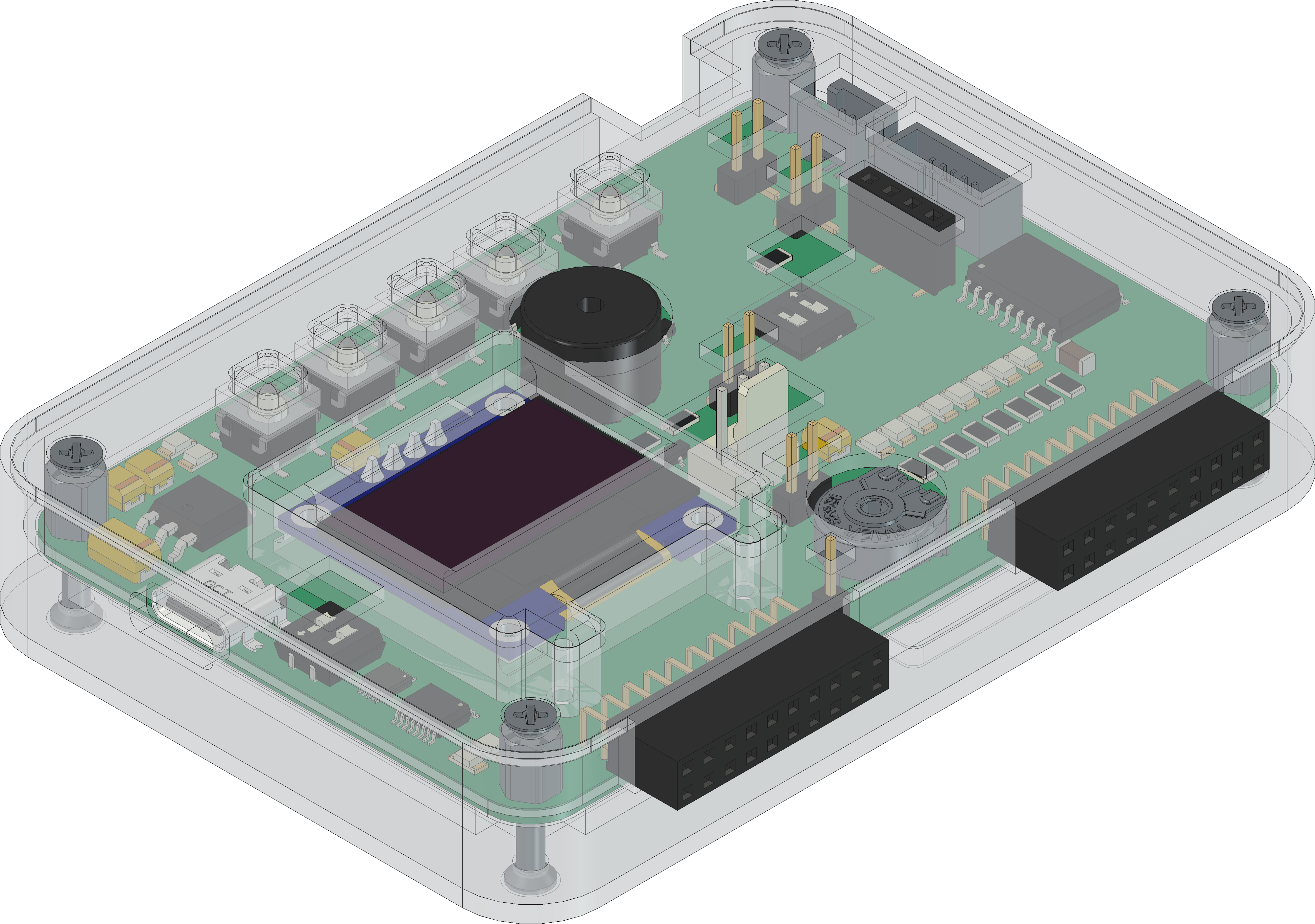
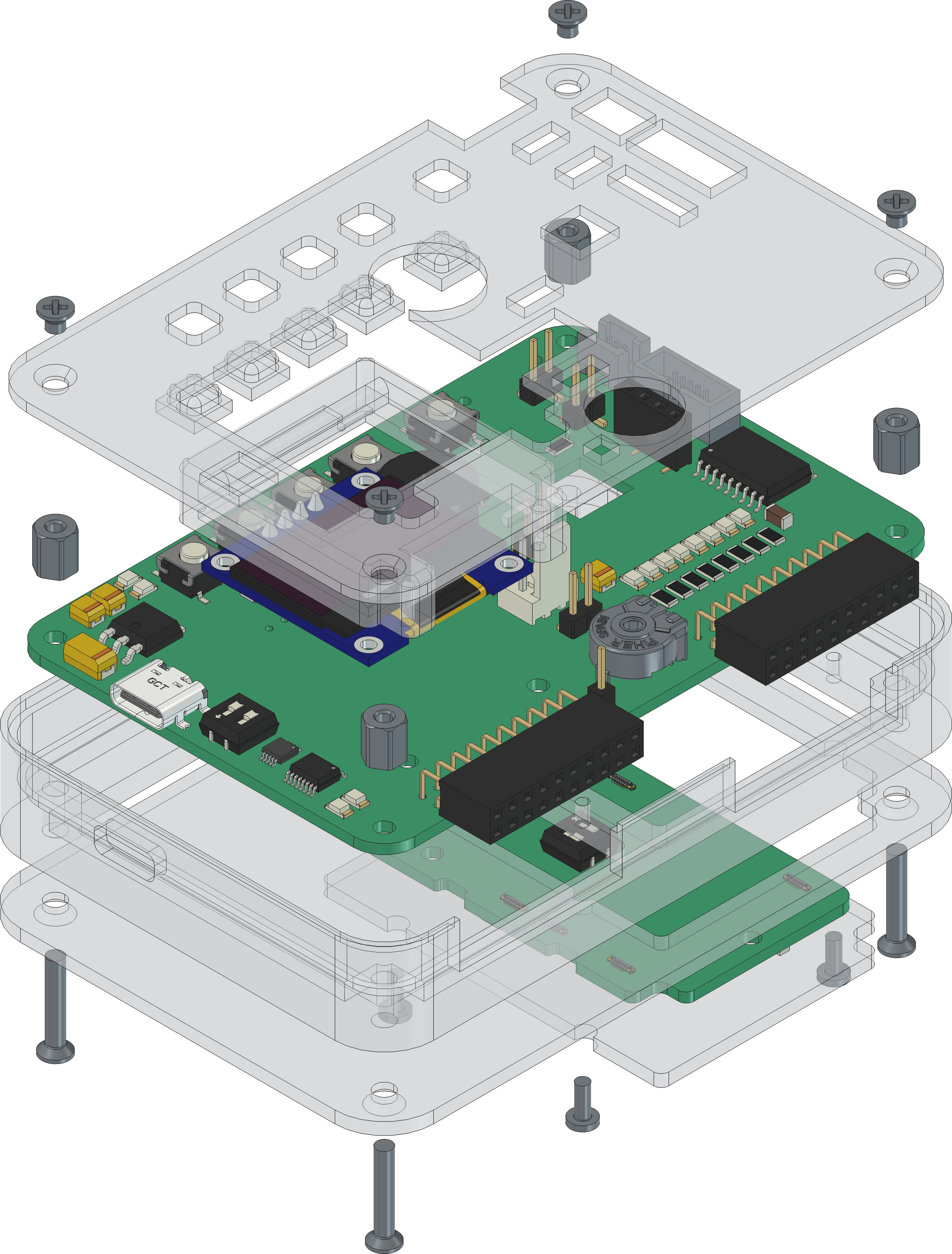
The pcb is created with KiCAD, the housing with FreeCAD. All files are built with github actions so that they are ready for a production environment.
The circuit board is populated on both sides (Top, Bottom). The best way for soldering the SMD components is within a vapor phase soldering system and for the THT components with a standard soldering system.


The housing has a tolerance of 0.2mm on each side of the case. So the pcb should fit perfectly in the housing. The tolerance can be modified with FreeCAD in the Parameter Spreadsheet.
| Type | Link | Description |
|---|---|---|
| FT230XS | USB/UART-Bridge | |
| TS3USB30 | USB-Multiplexer 1:2 | |
| TPS2116 | Power Mux with Manual and Priority Switchover | |
| TBD62783 | DMOS transistor array |
| Qty | Value | Footprint | References |
|---|---|---|---|
| 9 | 10k | Resistor_SMD:R_1206_3216Metric | R9, R10, R31, R32, R34, R41, R45, R50, R51 |
| 8 | Green | LED_SMD:LED_1206_3216Metric | D0, D1, D2, D3, D4, D5, D10, D11 |
| 7 | 100n | Capacitor_SMD:C_1206_3216Metric | C1, C4, C5, C6, C8, C12, C13 |
| 7 | 270 | Resistor_SMD:R_1206_3216Metric | R1, R2, R3, R4, R5, R6, R38 |
| 7 | 3k3 | Resistor_SMD:R_1206_3216Metric | R25, R26, R27, R28, R36, R37, R47 |
| 6 | MountingHole_Pad | MountingHole:MountingHole_2.7mm_M2.5_DIN965_Pad | H1, H2, H3, H4, H5, H6 |
| 5 | 103R012BB100 | Connector_Amphenol_SMD:AMPHENOL_103R012BB100 | J3, J7, J11, J12, J13 |
| 5 | AO3416 | Package_TO_SOT_SMD:SOT-23 | Q9, Q10, Q11, Q12, Q13 |
| 5 | SW_SPST | Button_Switch_SMD:SW_SPST_B3S-1000 | SW0, SW1, SW2, SW3, SW5 |
| 4 | 100u | Capacitor_Tantalum_SMD:CP_EIA-3528-21_Kemet-B | C3, C7, C10, C11 |
| 4 | Conn_01x02_Pin | Connector_PinHeader_2.54mm:PinHeader_1x02_P2.54mm_Vertical_SMD_Pin1Right | J2, J18, J19, J20 |
| 3 | 150 | Resistor_SMD:R_1206_3216Metric | R33, R35, R39 |
| 3 | 330 | Resistor_SMD:R_1206_3216Metric | R7, R8, R43 |
| 3 | 47R | Resistor_SMD:R_1206_3216Metric | R44, R48, R49 |
| 2 | 1k | Resistor_SMD:R_1206_3216Metric | R40, R42 |
| 2 | 5k1 | Resistor_SMD:R_1206_3216Metric | R29, R30 |
| 2 | BAT43 | Diode_SMD:D_MiniMELF | D14, D15 |
| 2 | Conn_01x01_Pin | Connector_Wire:SolderWire-0.75sqmm_1x01_D1.25mm_OD3.5mm | J8, J9 |
| 2 | Conn_02x10_Odd_Even | Connector_PinSocket_2.54mm:PinSocket_2x10_P2.54mm_Horizontal | J14, J15 |
| 2 | Red | LED_SMD:LED_1206_3216Metric | D7, D9 |
| 2 | SolderJumper_3_Open | Jumper:SolderJumper-3_P1.3mm_Open_RoundedPad1.0x1.5mm_NumberLabels | JP1, JP2 |
| 2 | Yellow | LED_SMD:LED_1206_3216Metric | D6, D12 |
| 1 | 10R | Resistor_SMD:R_1206_3216Metric | R46 |
| 1 | 10k | Potentiometer_THT:Potentiometer_Piher_PT-10-V10_Vertical | RV1 |
| 1 | 10n | Capacitor_SMD:C_0603_1608Metric | C2 |
| 1 | 1A | Fuse:Fuse_1206_3216Metric | F1 |
| 1 | 47u | Capacitor_Tantalum_SMD:CP_EIA-6032-28_Kemet-C | C9 |
| 1 | 70Ω/100Mhz/3A | Inductor_SMD:L_1206_3216Metric | FB1 |
| 1 | 74AHC1G14 | Package_TO_SOT_SMD:SOT-23-5 | U3 |
| 1 | B360A | Diode_SMD:D_SMA | D13 |
| 1 | BIN | Symbol:WEEE-Logo_4.2x6mm_SilkScreen | FID2 |
| 1 | Buzzer | Buzzer_Beeper:MagneticBuzzer_ProSignal_ABT-410-RC | BZ1 |
| 1 | Conn_01x01_Pin | Connector_PinHeader_2.54mm:PinHeader_1x01_P2.54mm_Vertical | J17 |
| 1 | Conn_01x03 | Connector_Molex:Molex_KK-254_AE-6410-03A_1x03_P2.54mm_Vertical | J16 |
| 1 | Conn_01x04 | Connector_PinSocket_2.54mm:PinSocket_1x04_P2.54mm_Vertical | J6 |
| 1 | Conn_01x04_Pin | Connector_PinSocket_2.54mm:PinSocket_1x04_P2.54mm_Vertical_SMD_Pin1Right | J10 |
| 1 | Conn_02x03_Odd_Even | Connector_Amphenol_SMD:AMPHENOL_20021221-00006T4LF | J4 |
| 1 | Conn_02x05_Odd_Even | Connector_Amphenol_SMD:AMPHENOL_20021521-00010T4LF | J5 |
| 1 | ESD | Symbol:ESD-Logo_6.6x6mm_SilkScreen | FID4 |
| 1 | FT230XS | Package_SO:SSOP-16_3.9x4.9mm_P0.635mm | U1 |
| 1 | LM1117DT-3.3 | Package_TO_SOT_SMD:TO-252-3_TabPin2 | U5 |
| 1 | LOGO | LOGO | G*** |
| 1 | MB85RC04V | Package_SO:SOIC-8_3.9x4.9mm_P1.27mm | U7 |
| 1 | OH | Symbol:OSHW-Logo2_7.3x6mm_SilkScreen | FID3 |
| 1 | QR | Images:QR_0x007e_very_small | FID1 |
| 1 | SW_DIP_x02 | Button_Switch_SMD:SW_DIP_SPSTx02_Slide_6.7x6.64mm_W6.73mm_P2.54mm_LowProfile_JPin | SW6 |
| 1 | TBD62783A | Package_SO:SOIC-18W_7.5x11.6mm_P1.27mm | U6 |
| 1 | TPS2116DRL | Package_TO_SOT_SMD:SOT-583-8 | U4 |
| 1 | TS3USB30EDGSR | Package_SO:VSSOP-10_3x3mm_P0.5mm | U2 |
| 1 | USB_C_Receptacle | Connector_USB:USB_C_Receptacle_GCT_USB4110 | J1 |
| 1 | n.B. | Capacitor_Tantalum_SMD:CP_EIA-3528-21_Kemet-B | C14 |
It measures 92.7 × 62.2 mm and has 2 copper layers, 1.6 mm thick.
121 parts, built around the FT230XS-R, 74AHC1G14GV, LM1117DT-3.3 and TBD62783APG. The full list of its parts is on this page, with links to each part's symbol and footprint where PCBKit's library has them.
From the 0x007E/mgc repository on GitHub, at the commit this page was made from: the board is pcb/MGC.kicad_pcb and its schematic pcb/MGC.kicad_sch. PCBKit opens the board in the browser, with nothing to install.
Its repository states no licence, so its author keeps all rights: ask 0x007E before reusing the design.


3mdeb/sd-mux
Control application for SD Wire imported from: https://git.tizen.org/cgit/tools/testlab/sd-mux/


twasilczyk/waterdrop-esphome
Waterdrop RO system smart Wi-Fi module for Home Assistant