4 layers189.4 × 59.1 mm

 caipiblack/STM32-CAN-Bus-board5
This is an STM32F042K6T6 based board that can be used to build sensors that communicate over a CAN bus
MCU Board is an open-source printed circuit board by caipiblack, from the caipiblack/STM32-CAN-Bus-board repository on GitHub, published under the GPL-3.0 licence. It is a 2-layer board of 50.8 × 68.6 mm with 26 parts on 40 nets, routed with 199 tracks and 0 vias.
It is built around the SN65HVD230D, MC34063AD and SM24CANB-02HTG, with the SMAJ33CA and SMAJ4750A-TP among its other parts. Its parts include 6 connectors, 5 capacitors, 5 resistors, 5 diodes and 2 ICs. It belongs with the interfaces and adapters and microcontroller boards boards of this library.


CAN Bus shield with external power supply (12V/24V) for NUCLEO-L432KC board.
All the pins of the NUCLEO-L432KC board are available on the connectors of the shield.
The available pins provide many peripherals (ADC, SPI, I2C, GPIO and more) that can be used for many projects (IOT sensors, security sensors, automation...)
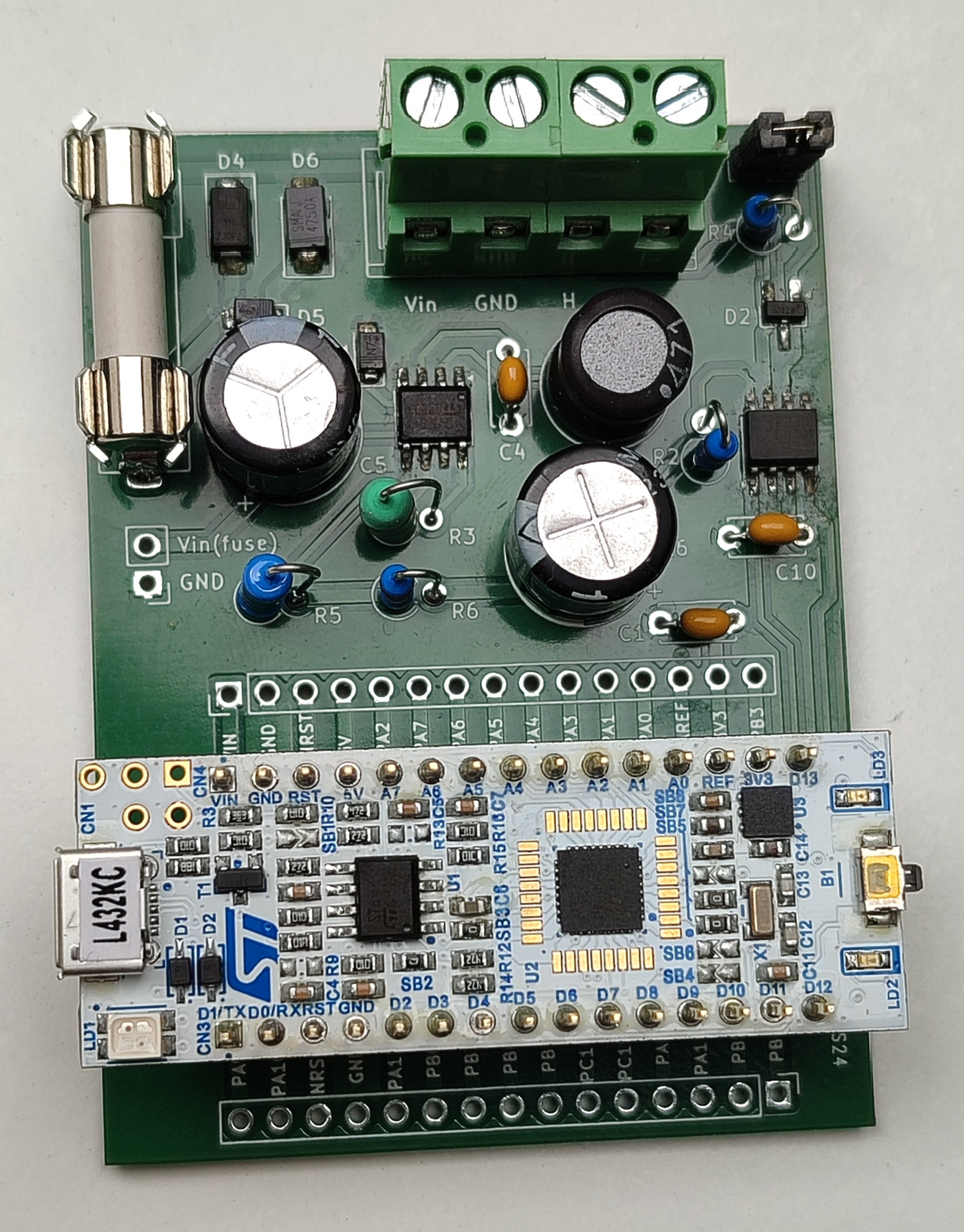
This part describe how the schematic was made, how to mount the PCB and how to test it.
IMPORTANT: This shield require some modifications on the Nucleo board to works (due to external supply) (see after)
The Kicad project as been created with the version 8.0.1 of Kicad.
Most of the symbols and footprints comes from the default libraries.
The custom footprints are stored in the custom folder near the Kicad project.
Setup Kicad on Ubuntu 24.04:
sudo add-apt-repository ppa:kicad/kicad-8.0-releases
sudo apt update
sudo apt install kicad
The last production files are stored in the directory hardware/rev_a/fab.
Some modifications are required to be able to power the Nucleo board from external 3V3 regulator (provided by the shield):
After these changes:
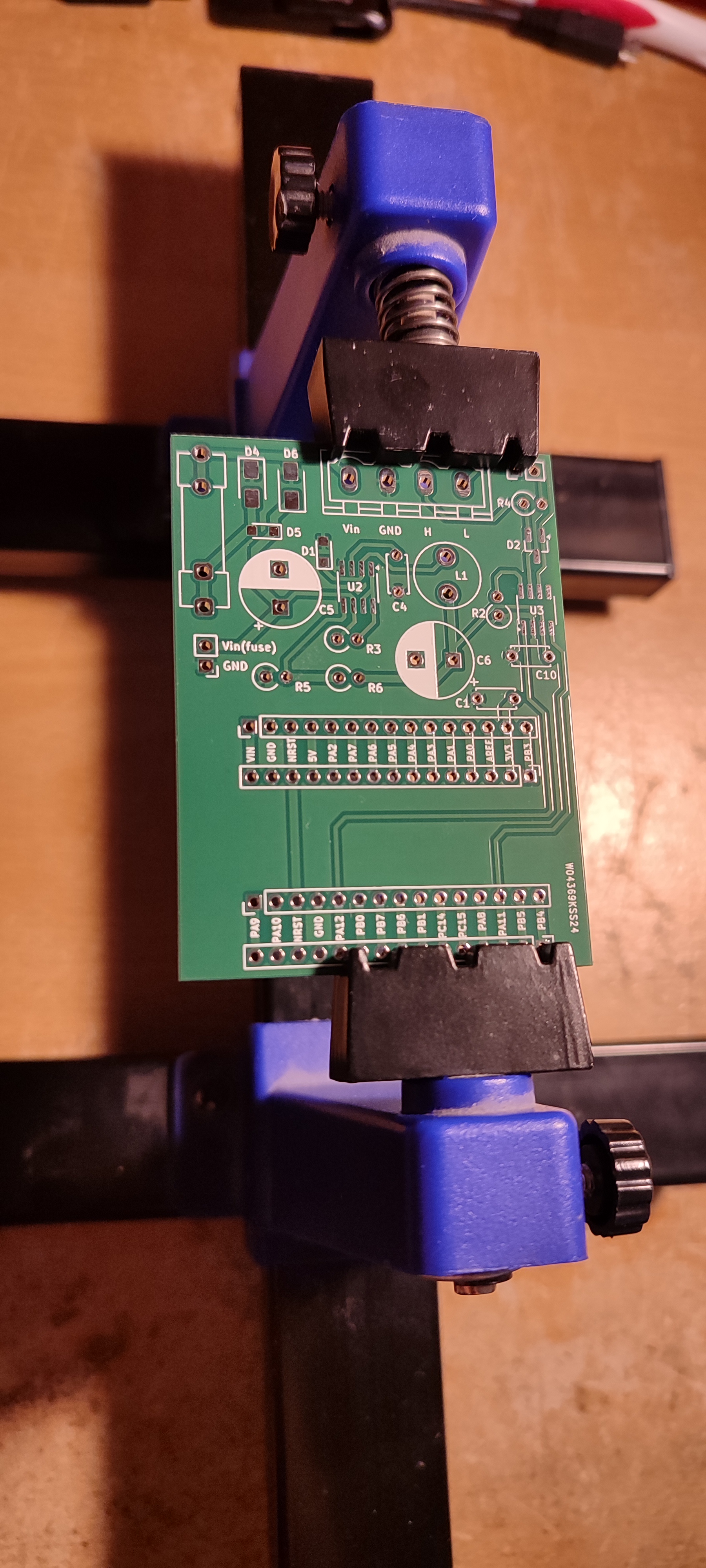
Mount the components on the board:
NUCLEO-L432KC board in the headers and solder the headers to the PCB (Doing it like this prevent issues with headers that are not perfectly vertical or parallel).Testing instructions:
NUCLEO-L432KC board from the headers.NUCLEO-L432KC board in the headers then turn on the power.
NUCLEO-L432KC board to the computer and flash it with the template project.sudo apt-get install can-utils
sudo modprobe vcan
sudo ip link add dev can0 type vcan
sudo ip link set up can0 type can bitrate 250000
candump -td -a can0candump you should see something like this: (000.000000) can0 71D [1] 00 '.'This repository comes with a demo software in the software directory: This software act like a CANopen node and permits to control the LED of the NUCLEO-L432KC board.
This guide also describe how to create a project from scratch for the STM32-CAN-Bus-board board.
The LED can be controlled by writing in the object at index 0x6001. (See examples at CANopenLinux section).
STM32CubeIDE from hereSTM32CubeProg from here. (This tool can be used to only flash the NUCLEO-L432KC board without the IDE)There are issues with STM32CubeIDE on Ubuntu 24.04 because it has a dependecy to libncurses5 and this is not available with this version of Ubuntu.
This dependency is required by the arm-none-eabi-gdb provided by ST.
To resolve the problem:
STM32CubeIDE instead of the version from .deb (as it will not check the dependency).arm-none-eabi-gdb or gdb-multiarch and create a link to provide arm-none-eabi-gdb:sudo apt install gdb-multiarch
sudo ln -s /usr/bin/gdb-multiarch /usr/bin/arm-none-eabi-gdbProject Properties -> C/C++ Build -> Environment -> PATH add /usr/bin at the first place to use arm-none-eabi-gdb provided by /usr/bin instead of ST directories.Base project creation:
STM32CubeIDE.File > New > STM32 Project.Board Selector.Commercial Part Number with NUCLEO-L432KC, then select it and press NextProject Name and Location, then press Finish..ioc file).PA0 to Reset_State as we don't have MCO clock source when the NUCLEO-L432KC is externaly powered from 3V3 (because MCO comes from the St-Link chip and it is not powered in this situation).Clock Configuration:System Clock Mux to use PLLCLKPLL Source Mux to MSIX48 and /4 to get 48Mhz in SYSCLK and APBsFor the integration of CANopenNode stack see the README of CanOpenSTM32:
CAN1CAN1Automatic Bus-Off ManagementAutomatic Wake-Up ModeAutomatic RetransmissionCAN1 is APB1 (datasheet). In my case with a clock of 48Mhz and desired bitrate of 250Kbit/s I set:
CANopenNode stack:TIM16TIM16TIM16 to get 1ms. Note that TIM16 use APB2 clock. In my case with a clock of 48Mhz I set:
CanOpenSTM32 somewhere in your computer see hereCANopenNode and CANopenNode_STM32 directories from the cloned repo and copy that in your project (from the IDE)CANopenNode and CANopenNode_STM32 to Source locations in Project Properties -> C/C++ General -> Paths and Symbols -> Source Locations. Then add an exclusion filter for example/ folder for CANopenNode folderCANopenNode and CANopenNode_STM32 to Project Properties -> C/C++ General -> Paths and Symbols -> Includes under GNU C itemsmain.c, add #include "CO_app_STM32.h":/* Private includes ----------------------------------------------------------*/
/* USER CODE BEGIN Includes */
#include "CO_app_STM32.h"
/* USER CODE END Includes */main.c file, call canopen_app_interrupt() when the timer ticks at 1ms:/* USER CODE BEGIN 4 */
void HAL_TIM_PeriodElapsedCallback(TIM_HandleTypeDef *htim) {
// Handle CANOpen app interrupts
if (htim == canopenNodeSTM32->timerHandle) {
canopen_app_interrupt();
}
}
/* USER CODE END 4 */main.c file, configure the CANopenNode stack and call the canopen_app_process() function in the main loop:int main(void)
{
// ...
/* Initialize all configured peripherals */
// ...
/* USER CODE BEGIN 2 */
CANopenNodeSTM32 canOpenNodeSTM32;
canOpenNodeSTM32.CANHandle = &hcan1;
canOpenNodeSTM32.HWInitFunction = MX_CAN1_Init;
canOpenNodeSTM32.timerHandle = &htim16;
canOpenNodeSTM32.desiredNodeID = 20;
canOpenNodeSTM32.baudrate = 250;
canopen_app_init(&canOpenNodeSTM32);
/* USER CODE END 2 */
/* Infinite loop */
/* USER CODE BEGIN WHILE */
while (1)
{
/* USER CODE END WHILE */
/* USER CODE BEGIN 3 */
canopen_app_process();PCB testing instructions.CANopenEditor and download the binaries linkEDSEditor.exe with wine:wine net481/EDSEditor.exeCANopenNode_STM32/DS301_profile.xpdCANopenLinux can be used as a gateway to communicate with CANopen devices using socket/stdio commands.
Setup the CAN interface:
sudo apt-get install can-utils
sudo modprobe vcan
# Do it only if can0 is not already mounted!
#sudo ip link add dev can0 type vcan
sudo ip link set up can0 type can bitrate 250000
Download and install CANopenLinux:
git clone https://github.com/CANopenNode/CANopenLinux.git
cd CANopenLinux
git submodule update --init --recursive
make
Read an OD entry from the computer:
./canopend can0 -i 1 -c "stdio"
20 r 0x1000 0
[0] 34 12 00 00
Write an OD entry from the computer:
./canopend can0 -i 1 -c "stdio"
20 w 0x6001 0 U32 0
[0] OK
In my example, 0x6001 controls the LED!
| Qty | Value | Footprint | References |
|---|---|---|---|
| 4 | Conn_01x15 | Connector_PinHeader_2.54mm:PinHeader_1x15_P2.54mm_Vertical | J1, J5, J6, J7 |
| 2 | 100n | Capacitor_THT:C_Disc_D5.0mm_W2.5mm_P5.00mm | C1, C10 |
| 2 | 10k | Resistor_THT:R_Axial_DIN0309_L9.0mm_D3.2mm_P2.54mm_Vertical | R2, R6 |
| 1 | 0R33 | Resistor_THT:R_Axial_DIN0309_L9.0mm_D3.2mm_P2.54mm_Vertical | R3 |
| 1 | 1000u | Capacitor_THT:CP_Radial_D10.0mm_P5.00mm | C6 |
| 1 | 100u | Capacitor_THT:CP_Radial_D10.0mm_P5.00mm | C5 |
| 1 | 120 | Resistor_THT:R_Axial_DIN0309_L9.0mm_D3.2mm_P2.54mm_Vertical | R4 |
| 1 | 470u | Inductor_THT:L_Radial_D8.7mm_P5.00mm_Fastron_07HCP | L1 |
| 1 | 680p | Capacitor_THT:C_Disc_D5.0mm_W2.5mm_P5.00mm | C4 |
| 1 | 6k2 | Resistor_THT:R_Axial_DIN0309_L9.0mm_D3.2mm_P2.54mm_Vertical | R5 |
| 1 | Bus | custom:PhoenixContact_MSTBVA_2,5_4-G-5,08_1x04_P5.08mm_Vertical_custom | J3 |
| 1 | Conn_01x02 | Connector_PinHeader_2.54mm:PinHeader_1x02_P2.54mm_Vertical | J2 |
| 1 | Fuse | Fuse:Fuseholder_Clip-5x20mm_Littelfuse_100_Inline_P20.50x4.60mm_D1.30mm_Horizontal | F1 |
| 1 | Jumper_2_Open | Connector_PinHeader_2.54mm:PinHeader_1x02_P2.54mm_Vertical | JP1 |
| 1 | MC34063AD | Package_SO:SOIC-8_3.9x4.9mm_P1.27mm | U2 |
| 1 | PMEG4020CERX | Diode_SMD:Nexperia_CFP3_SOD-123W | D1 |
| 1 | PMEG6020CER | Diode_SMD:Nexperia_CFP3_SOD-123W | D5 |
| 1 | SM24CANB-02HTG | Package_TO_SOT_SMD:SOT-23_Handsoldering | D2 |
| 1 | SMAJ33CA | Diode_SMD:D_SMA | D4 |
| 1 | SMAJ4750A | Diode_SMD:D_SMA | D6 |
| 1 | SN65HVD230 | Package_SO:SOIC-8_3.9x4.9mm_P1.27mm | U3 |

ilicmiljan/open-can-controller
Open-source CAN bus controller for BMW E9X instrument clusters (Firmware + PCB)


Poent/RC-Snowblower
Working on designing the impeller and auger portion of the snowblower. Switched from using a worm gear assembly to a custom ring and pinion setup using a spiral bevel gear.

JonasE99/HCP-Bridge
🚧 WIP – not yet manufactured or tested. KiCad PCB (one per door) connecting Hörmann series 4 garage door operators (ProMatic/SupraMatic, BUS/RJ12) to Loxone via ESP32-S3 and Wi-Fi.

Lathe-Mariel/CAN
回路 | 部品(Item) | 説明 | 数量(Qauntity) | Akizukiコード ---|---|---|---|--- U1 | ESP32-DevKitC | ESP32マイコン・ボード| 1 | 115673 IC1 | TJA1441AT | CANトランシーバ| 1 | 117464 R1, R2 | 60.4Ω 1608 | 終端抵抗 | 2 | R3, R4 | 120Ω 1608 | LED電流制限抵抗 |…


Stab-Rabbit-coding/Serenity-UAV
A functional, security conscious, Unmanned Aerial Vehicle based on the Firefly Class spacecraft Serenity from the 2002 show..
It measures 50.8 × 68.6 mm and has 2 copper layers, 1.6 mm thick.
26 parts, built around the SN65HVD230D, MC34063AD, SM24CANB-02HTG and SMAJ33CA. The full list of its parts is on this page, with links to each part's symbol and footprint where PCBKit's library has them.
From the caipiblack/STM32-CAN-Bus-board repository on GitHub, at the commit this page was made from: the board is hardware/rev_a/MCU_Board.kicad_pcb and its schematic hardware/rev_a/MCU_Board.kicad_sch. PCBKit opens the board in the browser, with nothing to install.
Its repository publishes it under the GPL-3.0 licence: you may reuse it on that licence's terms (keep the author's notice, and for a copyleft licence share your changes alike).