2 layers170.6 × 121.1 mm

 burgrp/nanook-mb2
NANOOK geothermal heat pump main board
Nanook mb is an open-source printed circuit board by burgrp, from the burgrp/nanook-mb repository on GitHub. It is a 2-layer board of 175 × 120 mm with 83 parts on 86 nets, routed with 756 tracks and 101 vias.
It is built around the DRV8833PW, SK22 and BC817. Its parts include 24 connectors, 18 resistors, 13 capacitors, 8 ICs and 5 diodes. It belongs with the STM32 boards of this library.


Nanook-mb is control board for open source NANOOK ground-water heat pump project. The board is responsible for:
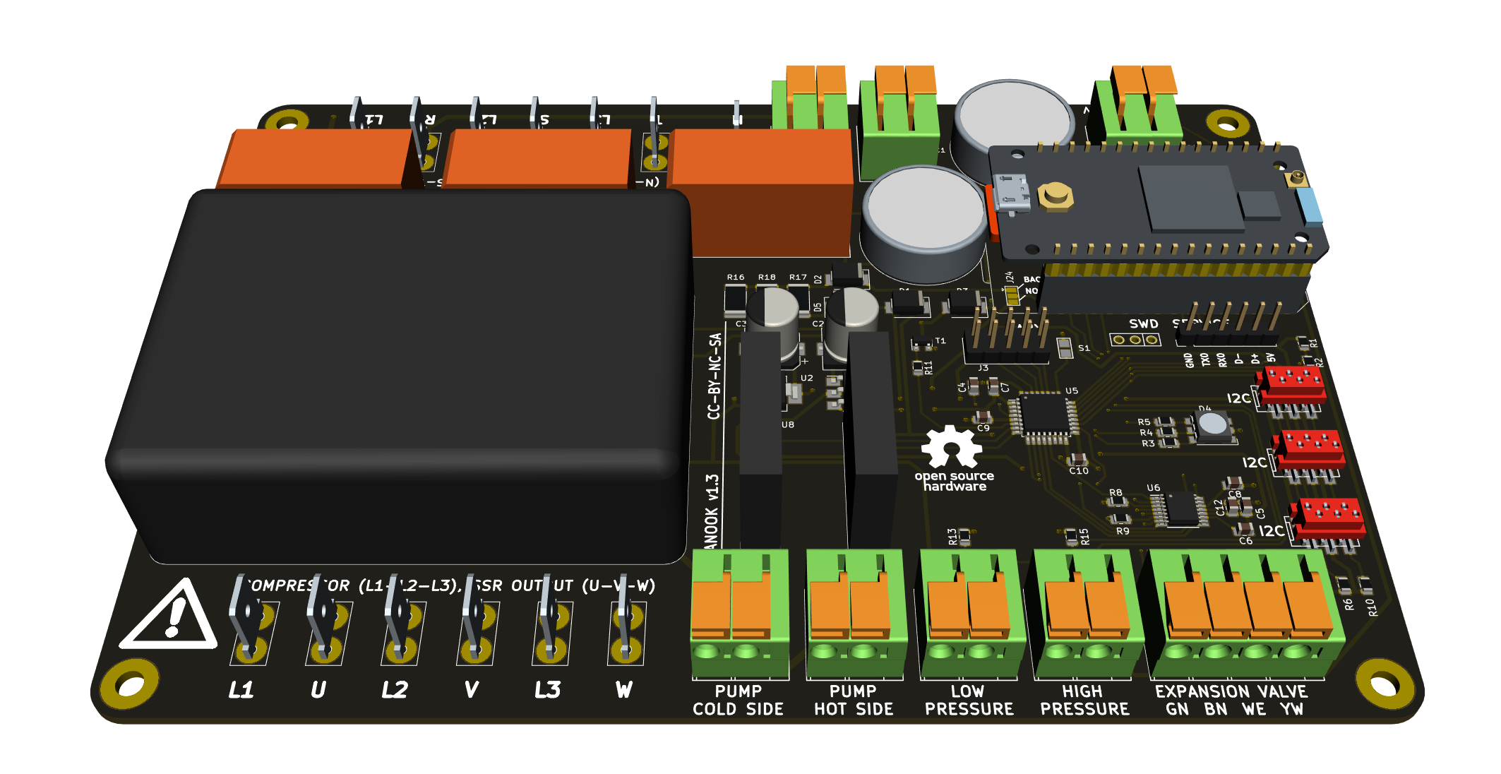
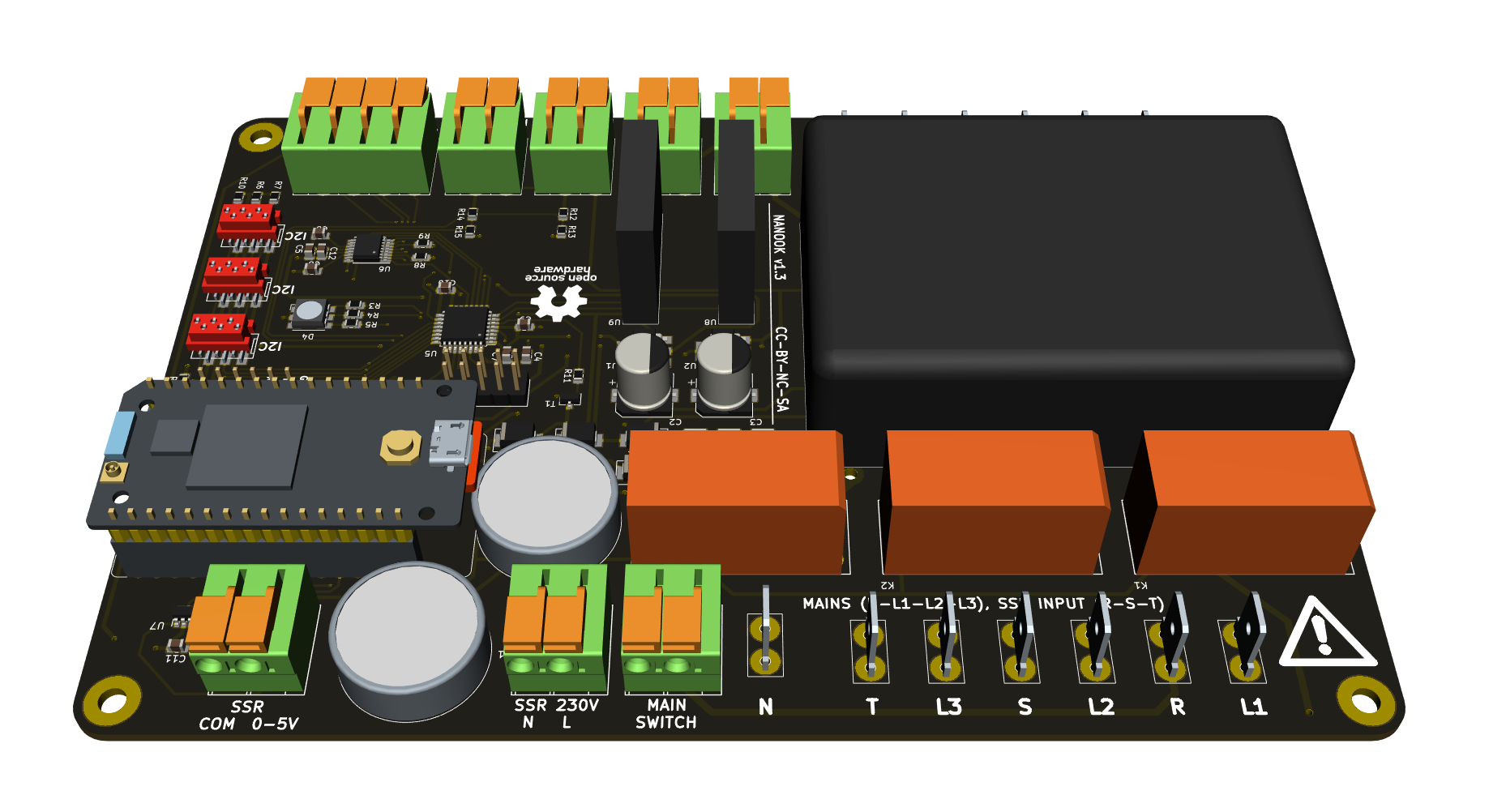
TBD: grounding, connectors, switching (rocker vs. ext. CB)
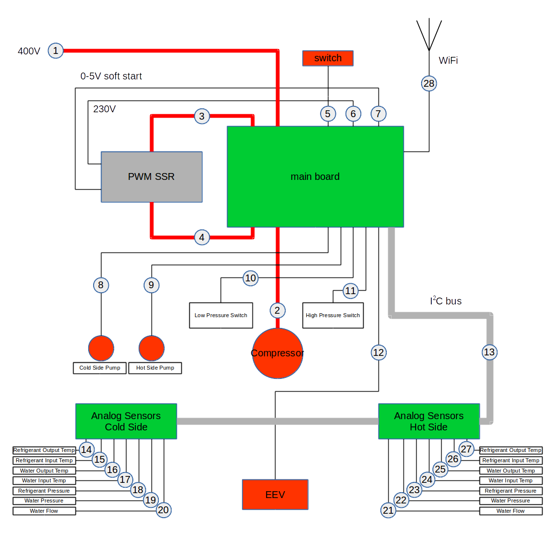
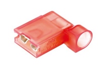
Connection to mains is done by flexible cable 5x 2.5mm2. Mains side should be connected to on-wall box with dedicated circuit breaker (3x16A). Board side end must be terminated with insulated Faston 6.3 connectors and connected to L1, L2, L3 and N terminals of the board. To avoid contact with metal chassis, use angled Fastons only.
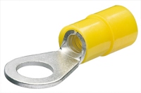
Ground wire must be terminated by crimp eye-type connector and mounted by screw to chassis.
This is, with #1, another high-current connection done by 3x 2.5mm2 cable. Both sides must be terminated by 6.3 Fastons.
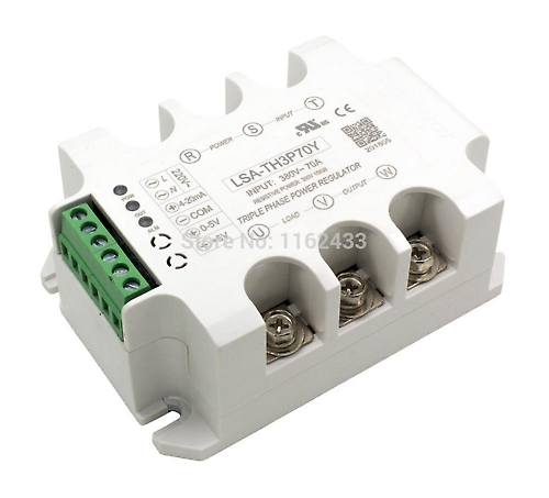
These are six 2.5mm2 wires terminated by 6.3 Fastons on board side and by eye on SSR side. Make sure all six wires (R, S, T, U, V, W) are connected to properly.
There is a rocker switch to turn heat pump ON and OFF. The switch just disconnects onboard power supply, which in turn opens onboard coil relays. This means that the board is still powered even with the rocker switch turned off.
These lines connects main board and PWM SSR control circuit. Two lines supply the control circuit with 230V AC power (#6). The other two are control signal 0-5V. Leave SSR contacts 4-20mA and +5V unconnected.
The main board directly controls primary (cold) and secondary (hot) side circulation pumps. Onboard SSRs are rated to 100W max power output.
Connections to safety pressure switches on low pressure and high pressure sides.
For wires of EEV stepper motor. Color coding for Carel valves is marked on PCB:
There are three connectors on board, all of them sharing single I2C bus. Analog sensor boards are connected by 6-wire flat cable with crimped Micro-Match connectors.
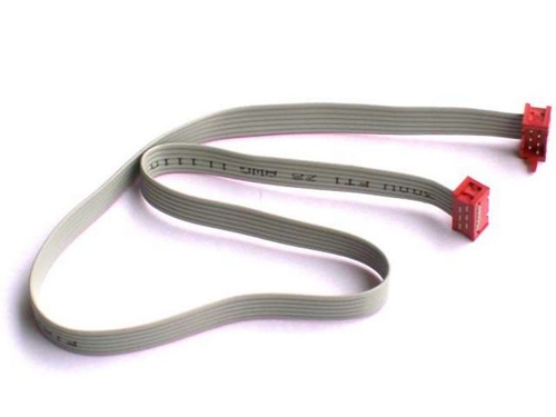
There may be two separate cables for each analog sensors board, or there may be single cable shared by both analog sensors boards.
Temperatures are measured by NTC 10K 1% 3950 thermistors.
There are waterproof thermistors with JST-XH connectors available. They may be used directly with no additional crimping needed.
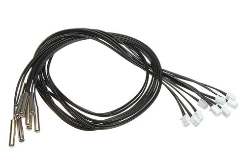
Thermistors should be tightly mounted on appropriate pipes, ideally with thermal conductive paste and outer environment insulation cover.
Thermistors are located as follows:
Pressure sensors are available either with other connectors than JST-XH or with no connector at all. You need to crimp proper three wire JST-XH connectors as:
and for Carel sensors with green, white and black wires as:
Pressure sensors are located as follows:
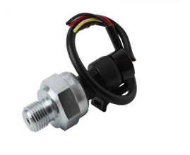
Ultisolar water pressure sensor 0...1.2MPa
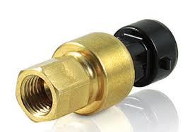
Carel SPKT refrigerant pressure sensor
Water flow sensors are available either with other connectors than JST-XH or with no connector at all. You need to crimp proper three wire JST-XH connectors as
Water sensors are located as follows:
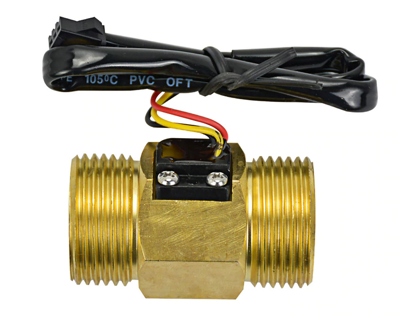
USC-HS10TA BSP is a suitable water flow sensor
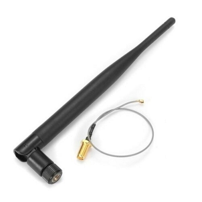
Main board is connected to network by WiFi. Although there is small chip antenna integrated on board, an external antenna is needed because of metal enclosure. Connect a 2.4GHz antenna by IPEX connector.
In order to compile and flash firmware, you need to install Node.js, openocd and arm-none-eabi GCC.
Source code is written our Silicon build system. Install Silicon by:
sudo npm install -g @device.farm/siliconAnd then build and flash by:
silicon build -dsfThe -f parameter instructs Silicon to flash the image using openocd, which should be connected to your MCU and listening on port 4444.
| Qty | Value | Footprint | References |
|---|---|---|---|
| 9 | 4k7 | Resistor_SMD:R_0805_2012Metric | R1, R2, R6, R7, R10, R12, R13, R14, R15 |
| 6 | 100n | Capacitor_SMD:C_0805_2012Metric | C4, C7, C9, C10, C11, C12 |
| 4 | SK22 | Diode_SMD:D_SMB | D1, D2, D3, D5 |
| 3 | 270R | Resistor_SMD:R_0805_2012Metric | R3, R4, R5 |
| 3 | 4R7/2W | Resistor_SMD:R_2512_6332Metric | R16, R17, R18 |
| 3 | RELAY_2 | Drake:RT314_Relay | K1, K2, K3 |
| 2 | 0R22 | Resistor_SMD:R_0805_2012Metric | R8, R9 |
| 2 | 1m | Capacitor_SMD:CP_Elec_8x10 | C2, C3 |
| 2 | 2F | Drake:BCE005R5C205FS | C1, C13 |
| 2 | G3MB-5V-SSR | Drake:G3MB-SSR | U8, U9 |
| 2 | NCP1117-3.3_SOT223 | Package_TO_SOT_SMD:SOT-223-3_TabPin2 | U1, U2 |
| 1 | 10n | Capacitor_SMD:C_0805_2012Metric | C6 |
| 1 | 10u | Capacitor_SMD:C_0805_2012Metric | C5 |
| 1 | 1K5 | Resistor_SMD:R_0805_2012Metric | R11 |
| 1 | 2.2M | Capacitor_SMD:C_0805_2012Metric | C8 |
| 1 | AUX | Connector_PinHeader_2.54mm:PinHeader_2x05_P2.54mm_Vertical | J3 |
| 1 | BC817 | Package_TO_SOT_SMD:SOT-23 | T1 |
| 1 | Compressor L1 | Drake:Tab-6.3 | J15 |
| 1 | Compressor L2 | Drake:Tab-6.3 | J16 |
| 1 | Compressor L3 | Drake:Tab-6.3 | J17 |
| 1 | DRV8833 | Drake:TSSOP-16_4.4x5mm_Pitch0.65mm-EP | U6 |
| 1 | E2V | Drake:DG142R-4-5.08 | J4 |
| 1 | GS3 | Jumper:SolderJumper-3_P1.3mm_Open_Pad1.0x1.5mm | J24 |
| 1 | HPS | Drake:DG142R-2-5.08 | J8 |
| 1 | I2C Aux | Drake:Micro-Match-FOB-6 | X4 |
| 1 | I2C Cold Side | Drake:Micro-Match-FOB-6 | X2 |
| 1 | I2C Hot Side | Drake:Micro-Match-FOB-6 | X3 |
| 1 | LED_RGB | Drake:LED_RGB_5050-6 | D4 |
| 1 | LPS | Drake:DG142R-2-5.08 | J5 |
| 1 | MCP4706A0T-E/CH | Package_TO_SOT_SMD:SOT-23-6 | U7 |
| 1 | Mains L1 | Drake:Tab-6.3 | J2 |
| 1 | Mains L2 | Drake:Tab-6.3 | J9 |
| 1 | Mains L3 | Drake:Tab-6.3 | J11 |
| 1 | Mains N | Drake:Tab-6.3 | J12 |
| 1 | Mean Well PM-15-5 | Drake:Mean-Well-PM-15-5 | U3 |
| 1 | NanoPi-Duo | Drake:NanoPi-Duo | M1 |
| 1 | Power Switch | Drake:DG142R-2-5.08 | J1 |
| 1 | Pump Cold Side | Drake:DG142R-2-5.08 | J6 |
| 1 | Pump Hot Side | Drake:DG142R-2-5.08 | J7 |
| 1 | SB2P | Drake:SB2P | S1 |
| 1 | SSR 0-5V | Drake:DG142R-2-5.08 | J14 |
| 1 | SSR 220 | Drake:DG142R-2-5.08 | J13 |
| 1 | SSR Input L1 | Drake:Tab-6.3 | J21 |
| 1 | SSR Input L2 | Drake:Tab-6.3 | J22 |
| 1 | SSR Input L3 | Drake:Tab-6.3 | J23 |
| 1 | SSR Output L1 | Drake:Tab-6.3 | J18 |
| 1 | SSR Output L2 | Drake:Tab-6.3 | J19 |
| 1 | SSR Output L3 | Drake:Tab-6.3 | J20 |
| 1 | STM32F030K6Tx | Package_QFP:LQFP-32_7x7mm_P0.8mm | U5 |
| 1 | SWD | Drake:SWD | X1 |
| 1 | Service | Connector_PinHeader_2.54mm:PinHeader_1x06_P2.54mm_Vertical | J10 |
The 78 most common of 83 parts.
It measures 175 × 120 mm and has 2 copper layers, 1.6 mm thick.
83 parts, built around the DRV8833PW, SK22 and BC817. The full list of its parts is on this page, with links to each part's symbol and footprint where PCBKit's library has them.
From the burgrp/nanook-mb repository on GitHub, at the commit this page was made from: the board is board/nanook-mb.kicad_pcb and its schematic board/nanook-mb.kicad_sch. PCBKit opens the board in the browser, with nothing to install.
Its repository states no licence, so its author keeps all rights: ask burgrp before reusing the design.


burgrp/accuwatt
6 channel electric boiler switch with tariff and I2C ports, based on ESP8266


RoboticsBrno/Robutek
Robůtek je robotická platforma založená na čipu ESP32-S3. Je velice rozšitiřelný, ale ze základu umí jezdit, kreslit fixou, jezdit po čáře, pohybovat se bludištěm. Programování je přes Jaculus.


CWRUbotix/Micromouse-2023-24
A fully autonomous maze-solving not-quite-mouse-sized robot.