4 layers32.4 × 38.1 mm

 bsiyoung/FPGA_Pre_Test
Testing power rails and oscillator waveforms for FPGA use.
FPGA Pre Test is an open-source printed circuit board by bsiyoung, from the bsiyoung/FPGA_Pre_Test repository on GitHub, published under the MIT licence. It is a 2-layer board of 50.5 × 34.8 mm with 50 parts on 29 nets, routed with 285 tracks and 39 vias.
It is built around the TPS62147RGXT, ZMR330FTA and T50201500000G, with the 219-4MST, ASDMB-25.000MHZ-XY-T and JS202011SCQN among its other parts. Its parts include 21 resistors, 11 capacitors, 4 ICs, 2 connectors and 2 switches. It belongs with the fPGA and programmable logic boards and the FPGA and CPLD boards of this library.


This simple project is for testing power rails and external oscillator to use them on FPGA circuit design.
| Directory | Description |
|---|---|
| calculation | files for calculation |
| datasheet | datasheets of components |
| diagrams | diagrams images |
| eda_model | EDA model files for KiCAD |
| kicad_proj | KiCAD project directory |
| pcb | PCB images and gerber file |
| readme_img | image for readme file |
| schematic | schematic jpg and pdf file |
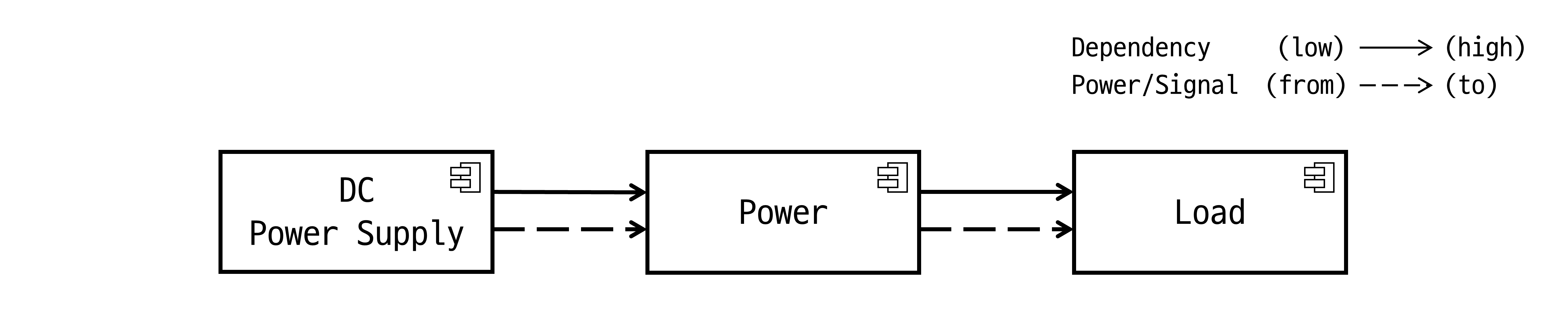
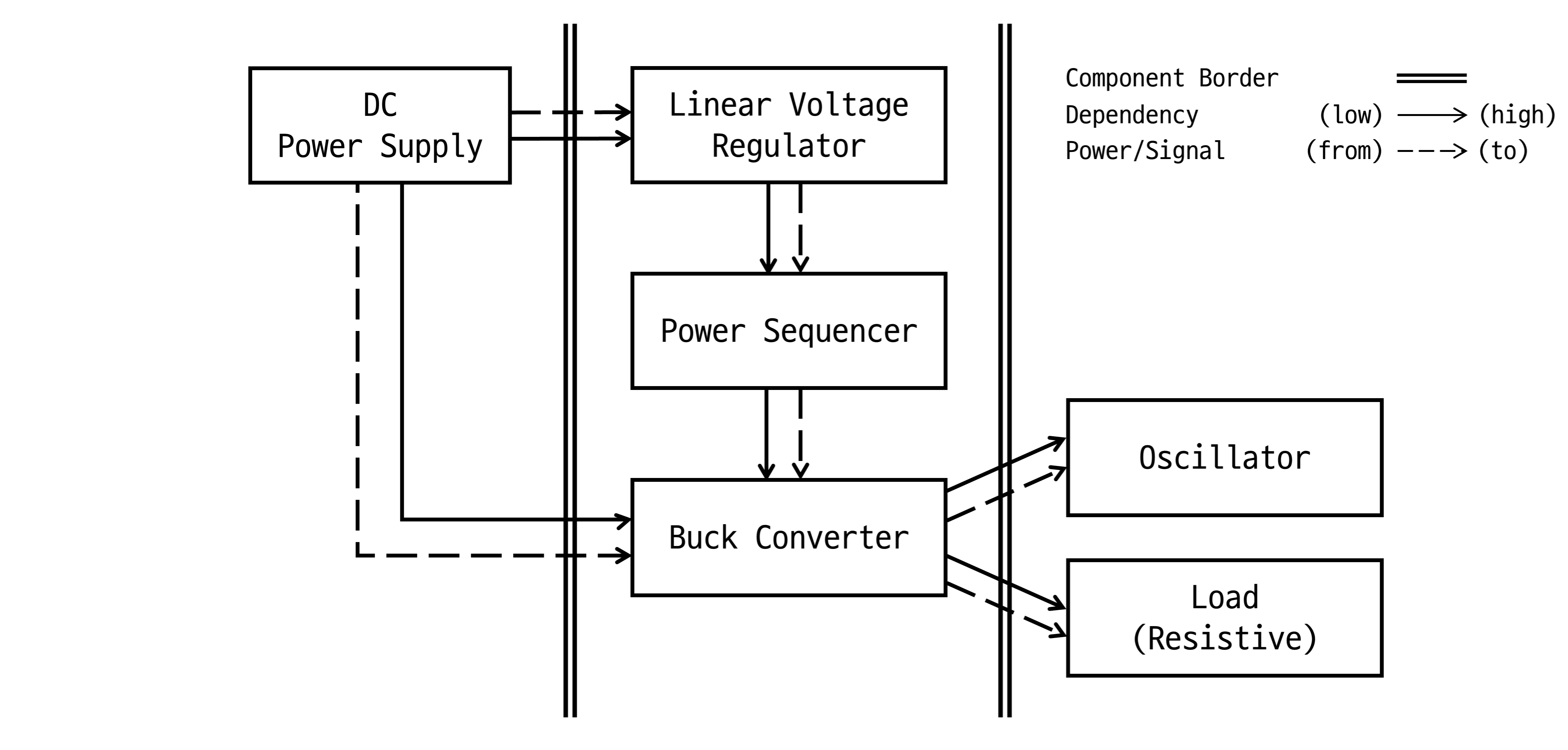
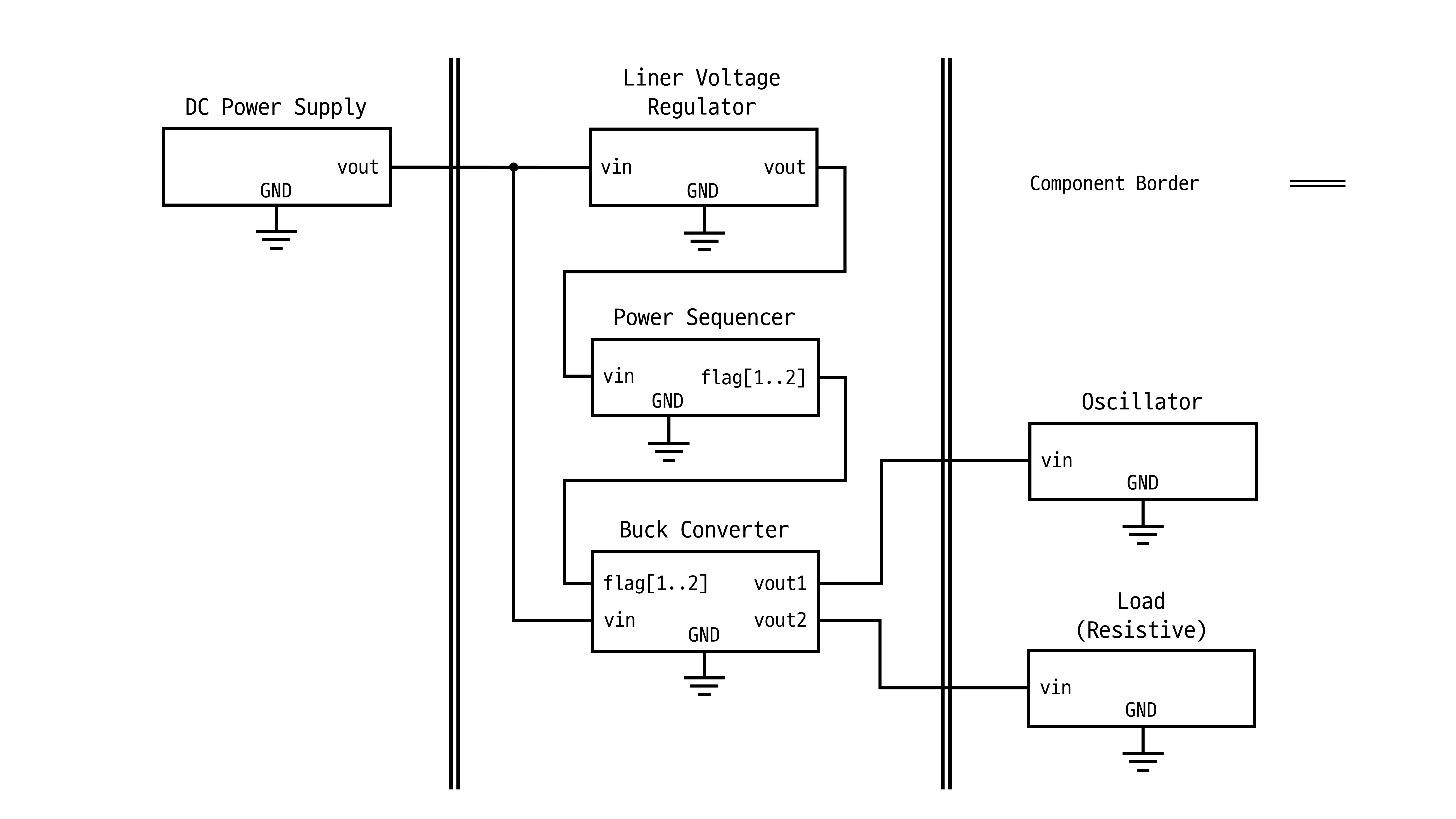
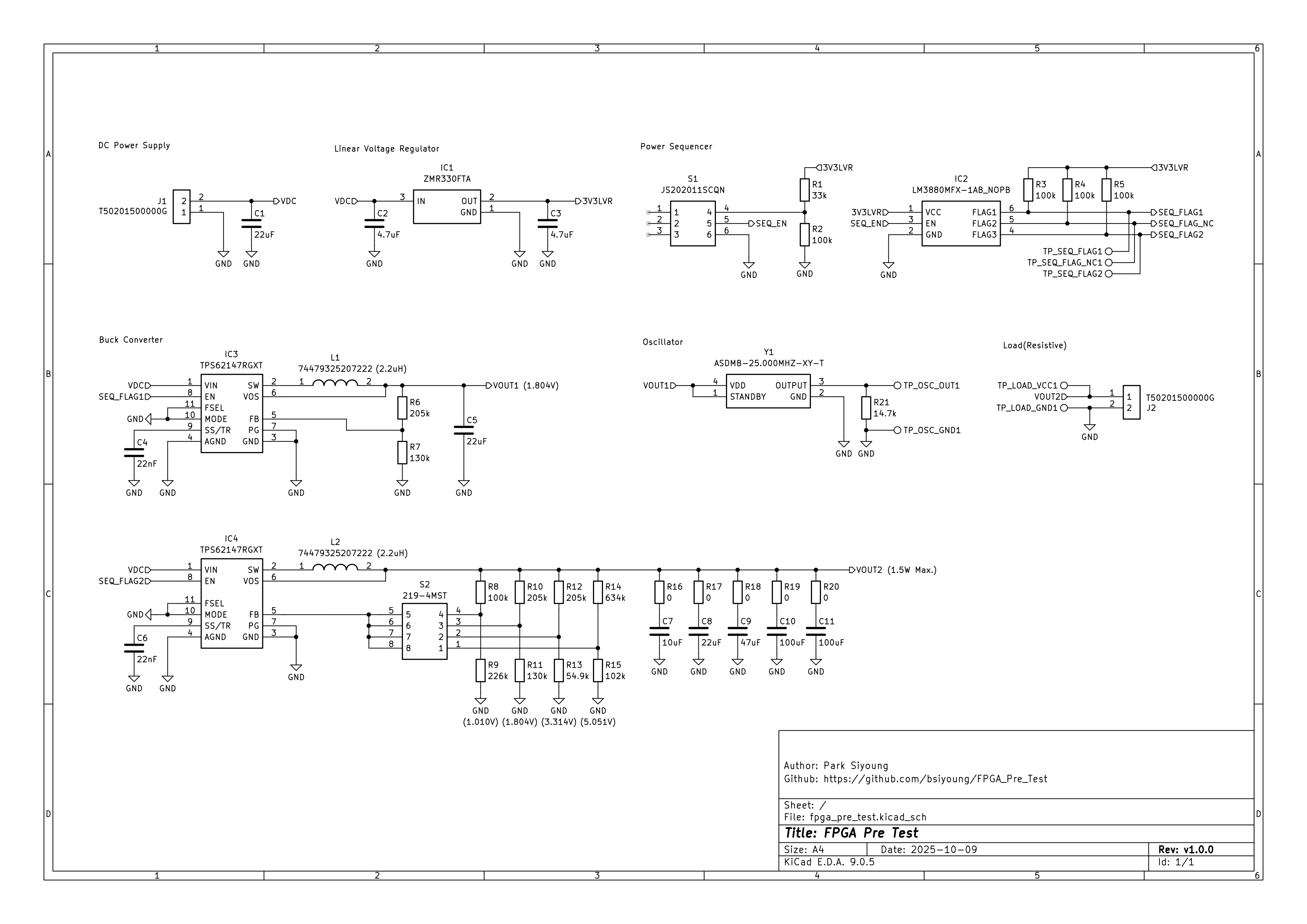
Footprints of resistors R16~20 will be used as solder jumper.
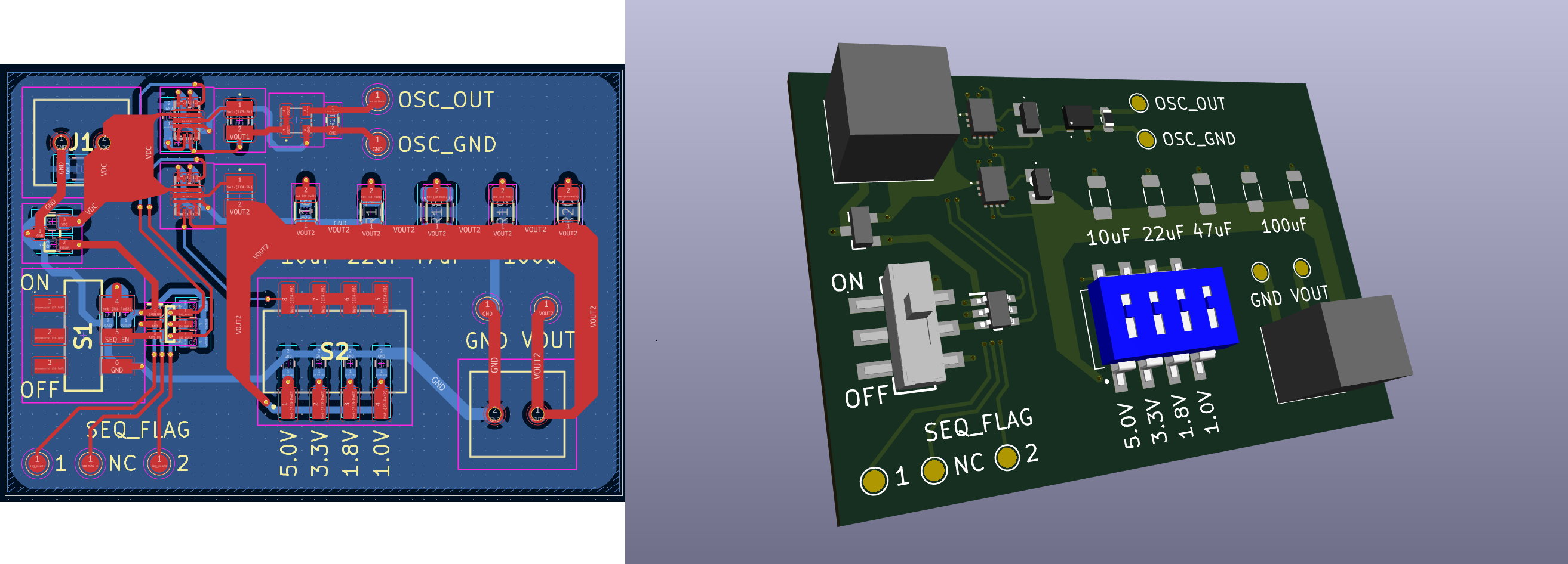
Manufacturer : JLC PCB
Gerber File : ./pcb/pcb_gerber.zip (zip file of ./kicad_proj/output)
| Qty | Value | Footprint | References |
|---|---|---|---|
| 7 | TestPoint | TestPoint:TestPoint_Pad_D1.5mm | TP_LOAD_GND1, TP_LOAD_VCC1, TP_OSC_GND1, TP_OSC_OUT1, TP_SEQ_FLAG_NC1, TP_SEQ_FLAG1, TP_SEQ_FLAG2 |
| 5 | 0 | Resistor_SMD:R_1206_3216Metric | R16, R17, R18, R19, R20 |
| 5 | 100k | Resistor_SMD:R_0603_1608Metric | R2, R3, R4, R5, R8 |
| 3 | 205k | Resistor_SMD:R_0603_1608Metric | R6, R10, R12 |
| 2 | 100uF | Capacitor_SMD:C_1206_3216Metric | C10, C11 |
| 2 | 130k | Resistor_SMD:R_0603_1608Metric | R7, R11 |
| 2 | 22nF | Capacitor_SMD:C_0402_1005Metric | C4, C6 |
| 2 | 22uF | Capacitor_SMD:C_0805_2012Metric | C5, C8 |
| 2 | 74479325207222 | 74479325207222:74479325207222 | L1, L2 |
| 2 | T50201500000G | T50201500000G:T50201500000G | J1, J2 |
| 2 | TPS62147RGXT | TPS62147RGXT:TPS62147RGXT | IC3, IC4 |
| 1 | 102k | Resistor_SMD:R_0603_1608Metric | R15 |
| 1 | 10uF | Capacitor_SMD:C_0603_1608Metric | C7 |
| 1 | 14.7k | Resistor_SMD:R_0603_1608Metric | R21 |
| 1 | 219-4MST | 219-4MST:2194MST | S2 |
| 1 | 226k | Resistor_SMD:R_0603_1608Metric | R9 |
| 1 | 22uF | Capacitor_SMD:C_1206_3216Metric | C1 |
| 1 | 33k | Resistor_SMD:R_0603_1608Metric | R1 |
| 1 | 4.7uF | Capacitor_SMD:C_0603_1608Metric | C3 |
| 1 | 4.7uF | Capacitor_SMD:C_0805_2012Metric | C2 |
| 1 | 47uF | Capacitor_SMD:C_1210_3225Metric | C9 |
| 1 | 54.9k | Resistor_SMD:R_0603_1608Metric | R13 |
| 1 | 634k | Resistor_SMD:R_0603_1608Metric | R14 |
| 1 | ASDMB-25.000MHZ-XY-T | ASDMB-25.000MHZ-XY-T:AbraconASDMB | Y1 |
| 1 | JS202011SCQN | JS202011SCQN:JS202011SCQN | S1 |
| 1 | LM3880MFX-1AB_NOPB | LM3880MFX-1AB_NOPB:SOT95P280X145-6N | IC2 |
| 1 | ZMR330FTA | ZMR330FTA:ZMR330FTA | IC1 |
It measures 50.5 × 34.8 mm and has 2 copper layers, 1.6 mm thick.
50 parts, built around the TPS62147RGXT, ZMR330FTA, T50201500000G and 219-4MST. The full list of its parts is on this page, with links to each part's symbol and footprint where PCBKit's library has them.
From the bsiyoung/FPGA_Pre_Test repository on GitHub, at the commit this page was made from: the board is kicad_proj/fpga_pre_test.kicad_pcb and its schematic kicad_proj/fpga_pre_test.kicad_sch. PCBKit opens the board in the browser, with nothing to install.
Its repository publishes it under the MIT licence: you may reuse it on that licence's terms (keep the author's notice, and for a copyleft licence share your changes alike).


Immortals-Robotics/MainBoard
Immortals main electronics for the Robocup Soccer Small-Size League

OE1KHZ/SlidersOfSociety-PCB
A CANbus controlled closed loop motor fader module based on Microchip's PIC18F25K83


aws/iot-expresslink
This device was designed and created for the AWS IoT ExpressLink Demo Badge Workshop, which was run at re:Invent 2022.

GMUCERG/fobos
Flexible Open-source workBench fOr Side-channel analysis (FOBOS)