
2 layers148 × 81 mm
Communicator pcb
Hack-a-Day/2025-Communicator_Badge
The 2025 Hackaday Supercon RF Communicator Badge
58 parts107MIT
 bschapendonk/sensorclock2
2.3" Digit clock running Windows 10 IoT Core with sensors powered by an Raspberry Pi 2 Model B
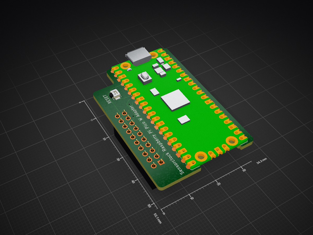
Picow adapter is an open-source printed circuit board by bschapendonk, from the bschapendonk/sensorclock repository on GitHub, published under the MIT licence. It is a 2-layer board of 34.3 × 52.1 mm with 4 parts on 39 nets, routed with 69 tracks and 6 vias.
It is built around the DMG2305UX. Its parts include 1 transistor, 1 connector and 1 switch. It belongs with the home automation and IoT and sensors and measurement boards and the RP2040 boards of this library.
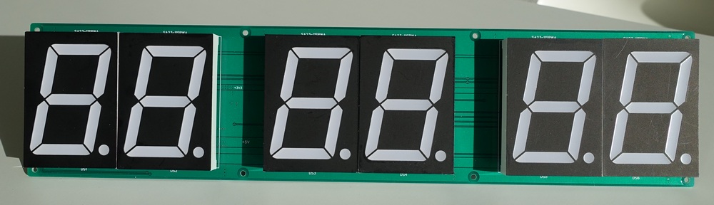
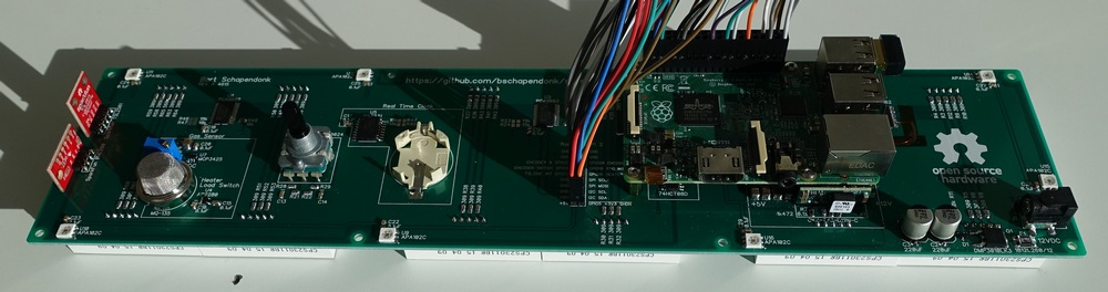
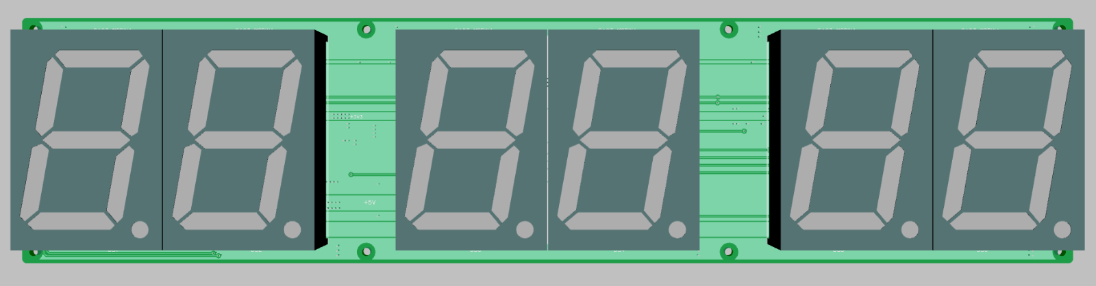
I'm a software engineer by trade and I was looking for a nice project to use Windows 10 IoT Core running on a Raspberry Pi 2 Model B. So I decided on an clock inspired by Steve Gardner's 6 Digit LED Clock project. Initially I only planned on the clock, but I ended up addeding a bunch of sensors that might be used for some "IoT" in the feature.
Everything is controlled thru I2C, except the RGB leds which use SPI, some GPIO's for the rotary encoder, interrupts from the sensors and control lines to turn off the +3V3 (to reset all I2C devices). Basically any MCU that has I2C, SPI and some GPIO's can be used.
The new Raspberry Pi 3 is pin compatible and runs even better
!!This is a work in progress, use at your own risk!!
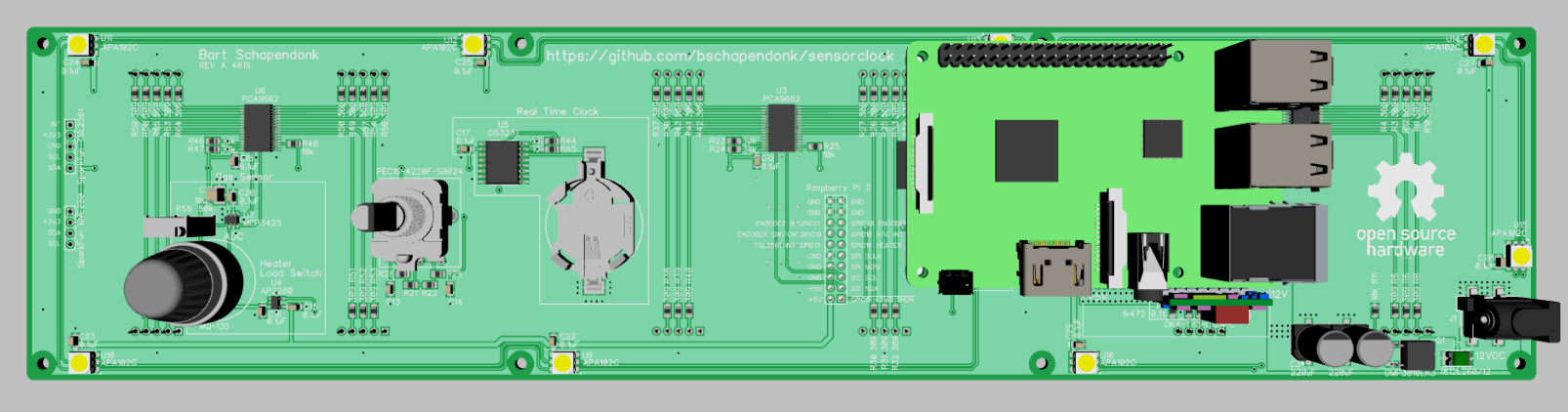
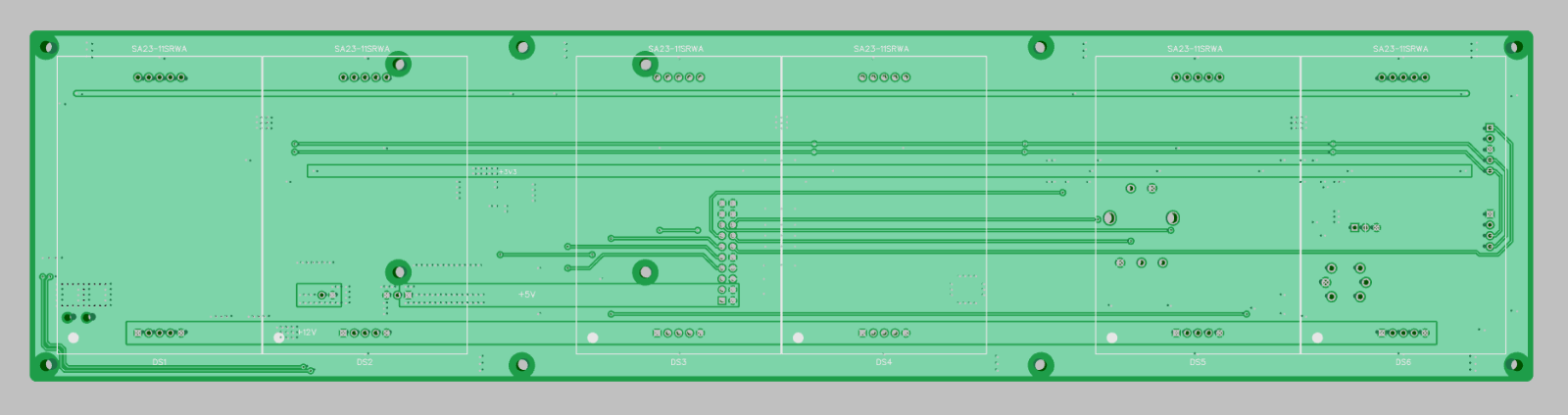
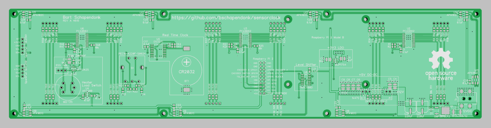
| Qty | Value | Footprint | References |
|---|---|---|---|
| 1 | DMG2305UX | Package_TO_SOT_SMD:SOT-23 | Q1 |
| 1 | RaspberryPi-PicoW | Module:Raspberry_Pi_Pico_SMT_THT | A1 |
| 1 | SW_Push | Button_Switch_SMD:SW_SPST_B3U-1000P | SW1 |
| 1 | Sensorclock | Connector_PinSocket_2.54mm:PinSocket_2x10_P2.54mm_Vertical | J1 |
It measures 34.3 × 52.1 mm and has 2 copper layers, 1.6 mm thick.
4 parts, built around the DMG2305UX. The full list of its parts is on this page, with links to each part's symbol and footprint where PCBKit's library has them.
From the bschapendonk/sensorclock repository on GitHub, at the commit this page was made from: the board is hardware/picow_adapter/picow_adapter.kicad_pcb and its schematic hardware/picow_adapter/picow_adapter.kicad_sch. PCBKit opens the board in the browser, with nothing to install.
Its repository publishes it under the MIT licence: you may reuse it on that licence's terms (keep the author's notice, and for a copyleft licence share your changes alike).
Hack-a-Day/2025-Communicator_Badge
The 2025 Hackaday Supercon RF Communicator Badge


hasenbanck/heteromycin
A 3D printer board using a powerfull STM32 MCU, TMC5160/TMC2160 driver and a Raspberry Pi or compatible SBC


m-labs/ionpak
A modern, low-cost universal controller for hot-cathode ionization vacuum gauges. (WIP)
