

4 layers70 × 100 mm
Txrx-1
brucemack/sdr2
This is a homebrew SDR rig with no dependency on external computers/soundcards/etc.
98 partsGPL-3.0

 brucemack/sdr2
This is a homebrew SDR rig with no dependency on external computers/soundcards/etc.
Util-1 is an open-source printed circuit board by brucemack, from the brucemack/sdr2 repository on GitHub, published under the GPL-3.0 licence. It is a 2-layer board of 50 × 80 mm with 46 parts on 27 nets, routed with 214 tracks and 46 vias.
It is built around the MAX4466EXK+T and TS5A3159ADBVRE4. Its parts include 13 capacitors, 10 resistors, 9 connectors, 6 ICs and 1 diode.
This is a homebrew SDR rig with no dependency on external computers/soundcards/etc.
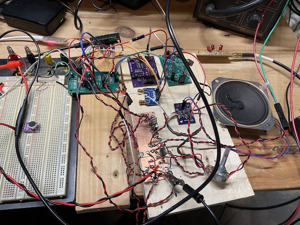
One-time setup of make process:
    git submodule update --init
    mkdir build
    cd build
    cmake -DPICO_BOARD=pico2 ..
Command used to flash code to board:
~/git/openocd/src/openocd -s ~/git/openocd/tcl -f interface/cmsis-dap.cfg -f target/rp2350.cfg -c "adapter speed 5000" -c "rp2350.dap.core1 cortex_m reset_config sysresetreq" -c "program main.elf verify reset exit"GP0 - (Reserved for UART0 TX)
GP1 - (Reserved for UART0 RX)
GP2 -
GP3 -
GP4 - I2S SCK out to PCM1804 ADC and PCM5100 DAC
GP5 - RST out to PCM1804 ADC
GP6 - I2S DIN in from PC1804 ADC
GP7 - I2S BCK out to PC1804 ADC
GP8 - I2S LRCK out to PC1804 ADC
GP9 - I2S DOUT out to PCM5100 DAC
GP10 - I2S BCK out to PCM5100 DAC
GP11 - I2S LRCK out to PCM5100 DAC
GP12 - User button input 0
GP13 - User button input 1
GP14 - PTT input
GP15 -
GP16 - I2C0 SDA for Si5351 (Addr 0x60)
GP17 - I2C0 SCL for Si5351 (Addr 0x60)
GP18 - I2C1 SDA for display and IO expander
GP19 - I2C1 SCL for display and IO expanderP0 - User indicator LED output
P1 - Audio amplifier enable (Low=enable output, high=shutdown amplifier)
P2 - ADC Input Select (Low=Microphone preamp out, High=QSD channel out)
P3 - TX band select 0
P4 - TX band select 1
P5 - RX band select 0
P6 - RX band select 1
P7 - Transmit PA enable (active low)See Horowitz and Hill (3rd ed, section 5.16, figure 5.88) for a description of the instrumentation amplifier configuration used on the receive board. Gain for this amplifier is controlled determined by 1 + 2 Rf / Rg. Notice that the feedback path is tapped after a 47 ohm resistor to set the output impedance of the stage.
Assuming Rf is 520, Rg is 100, the theoretical gain is about 11.
dBm = 30 + 20 * log(Vrms/sqrt(Z0))
Consider the PCM1863 ADC?
Consider the TS5A4624 analog switch (logic high = 2.4V w/ 5V supply)
Consider PCF8574A IO expander: https://www.ti.com/lit/ds/symlink/pcf8574a.pdf?ts=1728869550852&ref_url=https%253A%252F%252Fwww.mouser.com%252F
RF Transistor: https://www.nxp.com/docs/en/data-sheet/BFU590G.pdf
PCM1804 Datasheet PCM5100 Datasheet
The library gets built once in a parallel project:
    cd ~/pico
    mkdir CMSISDSP
    cd CMSISDSP
    git clone https://github.com/ARM-software/CMSIS-DSP.git
    git clone https://github.com/ARM-software/CMSIS_6.git
    cp $PICO_SDK_PATH/external/pico_sdk_import.cmake .
Then setup the CMakeLists.txt shown below and build:
    mkdir build
    cd build
    # IMPORTANT! pico2 build enables the generation of FPU instructions
    cmake -DPICO_BOARD=pico2 ..
    make -j4
What the CMakeLists.txt looks like:
cmake_minimum_required (VERSION 3.6)

# Pull in Pico SDK (must be before project)
include(pico_sdk_import.cmake)

set(HOME $ENV{HOME})
set(CMSISDSP ${HOME}/pico/CMSISDSP/CMSIS-DSP)
set(CMSISCORE ${HOME}/pico/CMSISDSP/CMSIS_6/CMSIS/Core)

# Define the project
project (cmsis-dsp VERSION 0.1)

# Initialise the Pico SDK
pico_sdk_init()

add_subdirectory(${CMSISDSP}/Source bin_dsp)

target_compile_options(CMSISDSP PUBLIC
    -Wsign-compare
    -Wdouble-promotion
    -Ofast -ffast-math
    -DNDEBUG
    -Wall -Wextra  -Werror
    -fshort-enums
    #-fshort-wchar
)
Example of referencing the built CMSIS-DSP library in a client project:
set(HOME $ENV{HOME})
target_include_directories(main PRIVATE
  ${HOME}/pico/CMSISDSP/CMSIS-DSP/Include
  ${HOME}/pico/CMSISDSP/CMSIS_6/CMSIS/Core/Include
)
target_link_libraries(main
  pico_stdlib
  ${HOME}/pico/CMSISDSP/build/bin_dsp/libCMSISDSP.a
)SDR2 Rig - Copyright (C) Bruce MacKinnon KC1FSZ, 2025
This program is free software: you can redistribute it and/or modify it under the terms of the GNU General Public License as published by the Free Software Foundation, either version 3 of the License, or (at your option) any later version.
This program is distributed in the hope that it will be useful, but WITHOUT ANY WARRANTY; without even the implied warranty of MERCHANTABILITY or FITNESS FOR A PARTICULAR PURPOSE. See the GNU General Public License for more details.
You should have received a copy of the GNU General Public License along with this program. If not, see https://www.gnu.org/licenses/.
FOR AMATEUR RADIO USE ONLY. NOT FOR COMMERCIAL USE WITHOUT PERMISSION.
| Qty | Value | Footprint | References |
|---|---|---|---|
| 4 | 10u | bruce-footprints:CPOL_0805_2012Metric_Pad1.18x1.45mm_HandSolder | C1, C2, C5, C6 |
| 4 | 1k | Resistor_SMD:R_0805_2012Metric_Pad1.20x1.40mm_HandSolder | R4, R5, R6, R9 |
| 4 | MountingHole | MountingHole:MountingHole_4mm | H1, H2, H3, H4 |
| 3 | 0.1uF | Capacitor_SMD:C_0805_2012Metric_Pad1.18x1.45mm_HandSolder | C8, C10, C13 |
| 3 | Conn_01x02 | Connector_PinHeader_2.54mm:PinHeader_1x02_P2.54mm_Vertical | J1, J4, J6 |
| 2 | 1M | Resistor_SMD:R_0805_2012Metric_Pad1.20x1.40mm_HandSolder | R7, R8 |
| 2 | 20k | Resistor_SMD:R_0805_2012Metric_Pad1.20x1.40mm_HandSolder | R1, R3 |
| 2 | Conn_01x06 | Connector_PinHeader_2.54mm:PinHeader_1x06_P2.54mm_Vertical | J3, J5 |
| 2 | TS5A3159ADBVR | Package_TO_SOT_SMD:SOT-23-6 | U5, U6 |
| 1 | 0.01uF | Capacitor_SMD:C_0805_2012Metric_Pad1.18x1.45mm_HandSolder | C9 |
| 1 | 0.39uF | Capacitor_SMD:C_0805_2012Metric_Pad1.18x1.45mm_HandSolder | C3 |
| 1 | 1.0uF | Capacitor_SMD:C_0805_2012Metric_Pad1.18x1.45mm_HandSolder | C4 |
| 1 | 100 | Resistor_SMD:R_0805_2012Metric_Pad1.20x1.40mm_HandSolder | R2 |
| 1 | 100k | bruce-footprints:POT_3362P | RV1 |
| 1 | 100pF | Capacitor_SMD:C_0805_2012Metric_Pad1.18x1.45mm_HandSolder | C12 |
| 1 | 10uF | Capacitor_SMD:C_0805_2012Metric_Pad1.18x1.45mm_HandSolder | C11 |
| 1 | 22k | Resistor_SMD:R_0805_2012Metric_Pad1.20x1.40mm_HandSolder | R10 |
| 1 | 3.3V | Connector_PinHeader_2.54mm:PinHeader_2x06_P2.54mm_Vertical | J8 |
| 1 | 5V | Connector_PinHeader_2.54mm:PinHeader_2x06_P2.54mm_Vertical | J7 |
| 1 | BATT | Connector_PinHeader_2.54mm:PinHeader_2x06_P2.54mm_Vertical | J9 |
| 1 | Conn_01x03 | Connector_PinHeader_2.54mm:PinHeader_1x03_P2.54mm_Vertical | J2 |
| 1 | FerriteBead | Inductor_SMD:L_0805_2012Metric_Pad1.15x1.40mm_HandSolder | FB1 |
| 1 | MAX4466EXK | Package_TO_SOT_SMD:SOT-353_SC-70-5_Handsoldering | U4 |
| 1 | NC | Capacitor_SMD:C_0805_2012Metric_Pad1.18x1.45mm_HandSolder | C7 |
| 1 | NCP1117-3.3_SOT223 | Package_TO_SOT_SMD:SOT-223-3_TabPin2 | U3 |
| 1 | NCP1117-5.0_SOT223 | Package_TO_SOT_SMD:SOT-223-3_TabPin2 | U2 |
| 1 | Red | LED_SMD:LED_0805_2012Metric_Pad1.15x1.40mm_HandSolder | D1 |
| 1 | TestPoint | TestPoint:TestPoint_Pad_2.5x2.5mm | TP1 |
| 1 | ~ | Package_SO:SOIC-8_3.9x4.9mm_P1.27mm | U1 |
brucemack/sdr2
This is a homebrew SDR rig with no dependency on external computers/soundcards/etc.

brucemack/sdr2
This is a homebrew SDR rig with no dependency on external computers/soundcards/etc.

brucemack/sdr2
This is a homebrew SDR rig with no dependency on external computers/soundcards/etc.

brucemack/sdr2
This is a homebrew SDR rig with no dependency on external computers/soundcards/etc.

brucemack/sdr2
This is a homebrew SDR rig with no dependency on external computers/soundcards/etc.

brucemack/sdr2
This is a homebrew SDR rig with no dependency on external computers/soundcards/etc.


Fairank/FieldDock
Compact iPhone companion hardware: editable PCB, mechanical CAD and portable firmware. Engineering prototype; original work available for noncommercial use.

ikeefe12/tankervision-pdb
Four-layer KiCad power distribution board for the TankerVision robot: USB-C PD / barrel-jack input, supercapacitor-backed rail for clean Jetson shutdown, and four firmware-controlled protected output ports.

TTembe/EEE3088F_2025
This repository contains the schematic, PCB layout, firmware, and documentation for the Power Subsystem of a maze-solving Micro-Mouse robot, developed as part of the EEE3088F course at the University of Cape Town.

TUDSSL/DIPS
This is the official public repository for DIPS: Debugger for Intermittently-Powered Systems. The repository consists of all components that make DIPS: - Hardware - Debugger Firmware - Emulator Firmware - Emulator Host…
It measures 50 × 80 mm and has 2 copper layers, 1.6 mm thick.
46 parts, built around the MAX4466EXK+T and TS5A3159ADBVRE4. The full list of its parts is on this page, with links to each part's symbol and footprint where PCBKit's library has them.
From the brucemack/sdr2 repository on GitHub, at the commit this page was made from: the board is hw/util-1/util-1.kicad_pcb and its schematic hw/audio-breakout/adc.kicad_sch. PCBKit opens the board in the browser, with nothing to install.
Its repository publishes it under the GPL-3.0 licence: you may reuse it on that licence's terms (keep the author's notice, and for a copyleft licence share your changes alike).