
2 layers

 brbcza/balanced-receiver
Balanced Audio Receiver
Balanced receiver is an open-source printed circuit board by brbcza, from the brbcza/balanced-receiver repository on GitHub, published under the GPL-3.0 licence. It is a 4-layer board of 70 × 76 mm with 139 parts on 84 nets, routed with 794 tracks and 117 vias.
It is built around the TPS5430DDA, 24LC256-I/P and LM1117DT-3.3, with the B340A among its other parts. Its parts include 60 capacitors, 42 resistors, 11 connectors, 8 ICs and 4 diodes. It belongs with the audio and music boards of this library.


The Balanced Audio Receiver is a versatile, compact PCB (Printed Circuit Board) designed for DIY audio enthusiasts, particularly for use as an input stage in custom speaker projects. The design integrates a balanced XLR 3-pin input and includes an onboard 5V buck converter to provide power for additional components, making it a comprehensive solution for audio applications that require both signal processing and power management.
This board is ideal for anyone looking to build high-quality audio systems, such as home audio setups or custom speaker projects, with a focus on clean, balanced audio signal processing.
[!NOTE]
The latest production files for the Balanced Audio Receiver can be downloaded from the latest release.
The Interactive BOM is also available in the latest release for easier component sourcing.
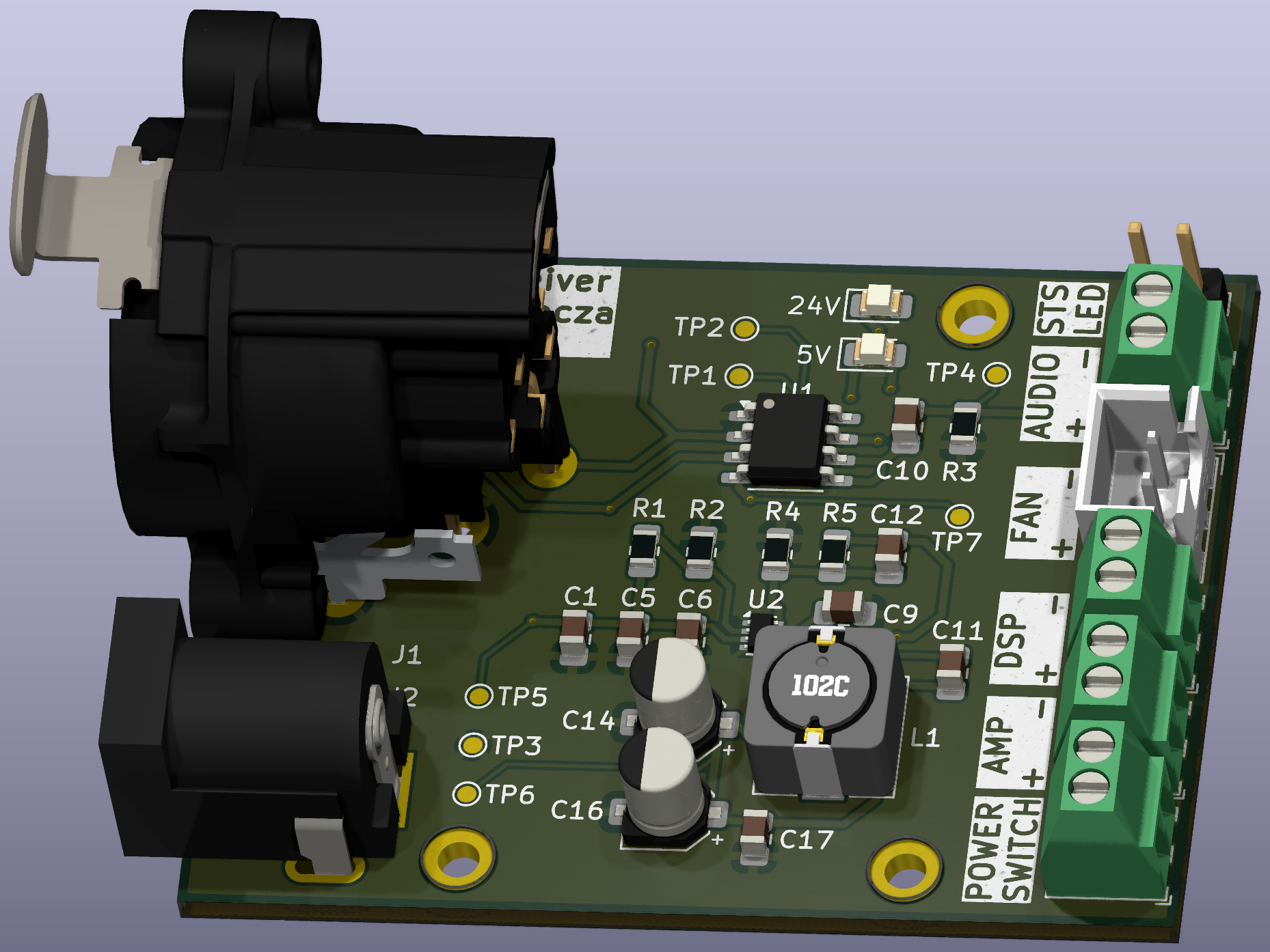
The Balanced Audio Receiver board incorporates several essential features to ensure high performance and flexibility:
The Balanced Audio Receiver PCB is designed to be as modular and flexible as possible. It is intended for use in various custom audio systems where space, signal integrity, and power efficiency are important considerations. The generated Bill of Materials from latest release will help to guide you in sourcing the components for assembly.
Interactive BOM
The interactive BOM can be found at the following link: Interactive BOM.
I welcome any contributions to the project. If you have suggestions for improvements, bug fixes, or want to add new features, feel free to submit pull requests or open issues.
The Balanced Audio Receiver is open-source hardware, licensed under the GPLv3 License. Feel free to modify and adapt the design for your own use, but please attribute the original project if you distribute it.
| Qty | Value | Footprint | References |
|---|---|---|---|
| 18 | 100nF | Capacitor_SMD:C_0805_2012Metric_Pad1.18x1.45mm_HandSolder | C20, C21, C27, C28, C30, C32, C33, C34, C35, C37, C38, C39, C41, C49, C50, C53 +2 |
| 16 | 10kΩ | Resistor_SMD:R_0805_2012Metric_Pad1.20x1.40mm_HandSolder | R2, R4, R7, R16, R21, R22, R23, R24, R25, R26, R31, R32, R33, R34, R35, R36 |
| 13 | 10uF | Capacitor_SMD:C_0805_2012Metric_Pad1.18x1.45mm_HandSolder | C1, C2, C3, C4, C15, C16, C31, C36, C40, C48, C51, C52, C55 |
| 5 | 10k | Resistor_SMD:R_0805_2012Metric_Pad1.20x1.40mm_HandSolder | R10, R42, R43, R45, R46 |
| 5 | 1uF | Capacitor_SMD:C_0805_2012Metric_Pad1.18x1.45mm_HandSolder | C22, C46, C47, C60, C61 |
| 4 | 22pF | Capacitor_SMD:C_0805_2012Metric_Pad1.18x1.45mm_HandSolder | C11, C12, C23, C24 |
| 4 | 6.2kΩ | Resistor_SMD:R_0805_2012Metric_Pad1.20x1.40mm_HandSolder | R17, R18, R27, R28 |
| 4 | 680pF | Capacitor_SMD:C_0805_2012Metric_Pad1.18x1.45mm_HandSolder | C44, C45, C58, C59 |
| 4 | 8.2kΩ | Resistor_SMD:R_0805_2012Metric_Pad1.20x1.40mm_HandSolder | R19, R20, R29, R30 |
| 4 | 820pF | Capacitor_SMD:C_0805_2012Metric_Pad1.18x1.45mm_HandSolder | C42, C43, C56, C57 |
| 4 | MountingHole_Pad_MP | MountingHole:MountingHole_2.2mm_M2_DIN965_Pad_TopBottom | H1, H2, H3, H4 |
| 3 | 18kΩ | Resistor_SMD:R_0805_2012Metric_Pad1.20x1.40mm_HandSolder | R11, R12, R37 |
| 3 | 2.2kΩ | Resistor_SMD:R_0805_2012Metric_Pad1.20x1.40mm_HandSolder | R6, R13, R15 |
| 3 | Conn_01x03_Pin | Connector_JST:JST_XH_B3B-XH-A_1x03_P2.50mm_Vertical | J3, J9, J10 |
| 3 | Conn_01x04_Pin | Connector_PinHeader_2.54mm:PinHeader_1x04_P2.54mm_Vertical | J6, J7, J8 |
| 2 | 10nF | Capacitor_SMD:C_0805_2012Metric_Pad1.18x1.45mm_HandSolder | C5, C6 |
| 2 | 1uH | Inductor_SMD:L_APV_APH0420 | L3, L4 |
| 2 | 220uF | Capacitor_SMD:CP_Elec_6.3x7.7 | C7, C8 |
| 2 | 22uF | Capacitor_SMD:CP_Elec_4x5.4 | C13, C14 |
| 2 | 22uH | Inductor_SMD:L_APV_ANR6028 | L1, L2 |
| 2 | 470pF | Capacitor_SMD:C_0805_2012Metric_Pad1.18x1.45mm_HandSolder | C18, C19 |
| 2 | B340A | Diode_SMD:D_SMA_Handsoldering | D2, D3 |
| 2 | OPA1612AxD | Package_SO:SOIC-8_3.9x4.9mm_P1.27mm | U7, U8 |
| 2 | PMOS | Package_TO_SOT_SMD:SOT-23 | Q5, Q6 |
| 2 | TPS5430DDA | Package_SO:TI_SO-PowerPAD-8 | U1, U2 |
| 1 | 100kΩ | Resistor_SMD:R_0805_2012Metric_Pad1.20x1.40mm_HandSolder | R1 |
| 1 | 100Ω | Resistor_SMD:R_0805_2012Metric_Pad1.20x1.40mm_HandSolder | R8 |
| 1 | 12.288MHz | Crystal:Crystal_SMD_3225-4Pin_3.2x2.5mm | Y2 |
| 1 | 1kΩ | Resistor_SMD:R_0805_2012Metric_Pad1.20x1.40mm_HandSolder | R14 |
| 1 | 24LC256 | Package_SO:SOIC-8_3.9x4.9mm_P1.27mm | U6 |
| 1 | 3.3k | Resistor_SMD:R_0805_2012Metric_Pad1.20x1.40mm_HandSolder | R3 |
| 1 | 3.3kΩ | Resistor_SMD:R_0805_2012Metric_Pad1.20x1.40mm_HandSolder | R5 |
| 1 | 3.3nF | Capacitor_SMD:C_0805_2012Metric_Pad1.18x1.45mm_HandSolder | C25 |
| 1 | 475Ω | Resistor_SMD:R_0805_2012Metric_Pad1.20x1.40mm_HandSolder | R9 |
| 1 | 47k | Resistor_SMD:R_0805_2012Metric_Pad1.20x1.40mm_HandSolder | R44 |
| 1 | 47pF | Capacitor_SMD:C_0805_2012Metric_Pad1.18x1.45mm_HandSolder | C17 |
| 1 | 47uF | Capacitor_SMD:CP_Elec_5x5.4 | C9 |
| 1 | 56nF | Capacitor_SMD:C_0805_2012Metric_Pad1.18x1.45mm_HandSolder | C26 |
| 1 | 600mA | balanced-receiver:Fuse_1812_4532Metric_Pad1.30x3.40mm_HandSolder | F1 |
| 1 | 9V | Diode_SMD:D_SOD-123 | D1 |
| 1 | ADAU1701 | Package_QFP:LQFP-48_7x7mm_P0.5mm | U5 |
| 1 | Conn_01x02_Pin | Connector_PinHeader_2.54mm:PinHeader_1x02_P2.54mm_Vertical | J12 |
| 1 | Conn_01x02_Pin | Connector_JST:JST_XH_B2B-XH-A_1x02_P2.50mm_Vertical | J4 |
| 1 | Conn_02x04_Odd_Even | Connector_PinHeader_2.54mm:PinHeader_2x04_P2.54mm_Vertical | J5 |
| 1 | LED | LED_SMD:LED_0805_2012Metric_Pad1.15x1.40mm_HandSolder | D4 |
| 1 | LM1117DT-3.3 | Package_TO_SOT_SMD:SOT-223-3_TabPin2 | U3 |
| 1 | PNP | Package_TO_SOT_SMD:SOT-23 | Q2 |
| 1 | Power | Connector_JST:JST_XH_B2B-XH-A_1x02_P2.50mm_Vertical | J1 |
| 1 | Q_PMOS_GDS | Package_TO_SOT_SMD:SOT-23 | Q1 |
| 1 | Screw_Terminal_01x02 | balanced-receiver:JST_XH_B2B-XH-AM_1x02_P2.50mm_Vertical | J2 |
| 1 | THAT1240 | Package_SO:SOIC-8_3.9x4.9mm_P1.27mm | U4 |
It measures 70 × 76 mm and has 4 copper layers, 1.6 mm thick.
139 parts, built around the TPS5430DDA, 24LC256-I/P, LM1117DT-3.3 and B340A. The full list of its parts is on this page, with links to each part's symbol and footprint where PCBKit's library has them.
From the brbcza/balanced-receiver repository on GitHub, at the commit this page was made from: the board is balanced-receiver.kicad_pcb and its schematic adau_1701.kicad_sch. PCBKit opens the board in the browser, with nothing to install.
Its repository publishes it under the GPL-3.0 licence: you may reuse it on that licence's terms (keep the author's notice, and for a copyleft licence share your changes alike).

Alia5/PiCCANTE
PiCCANTE is a powerful tool for exploring and reversing CAN busses of vehicles, based on Raspberry Pi Pico (any model)

CuriousMotor/Onyx-Stepper-Motherboard
The successor of the iconic Arduino-CNC-shield

JohnDecebal/UNDR
UNDR AUTO is a fully automatic WDT (Weiss Distribution Technique) tool designed for espresso enthusiasts. This open-source DIY project combines 3D printed parts with electronic and mechanical components to create a…

jeji/orange_juice
A orange pi zero shield board for 3D printer with klipper features

jeji/orange_juice_2
For Orange Pi zero 2 with klipper and more advance feature


durveshpathak1989/kicad-local-agent
Free local Ollama agent for generating and validating KiCad project files