
4 layers45.1 × 45.1 mm
SuperPower uC KiCad
SuperPower/Artemis
All hardware designs and products you can find in this repository is licensed under CERN Open Hardware Licence Version 2 - Weakly Reciprocal
99 parts2

a PCB of PCF8563 RTC with Grove I2C for M5Stack and M5Atom synchronized with NTP
Bf-027 is an open-source printed circuit board by botanicfields, from the botanicfields/PCB-RTC-PCF8563-for-M5 repository on GitHub, published under the CC0-1.0 licence. It is a 2-layer board of 44 × 44 mm with 25 parts on 13 nets, routed with 98 tracks and 34 vias.
It is built around the PCF8563T/5, XC6206P332MR and CR2032. Its parts include 5 capacitors, 4 resistors, 4 diodes, 3 connectors and 2 ICs. It belongs with the radio and wireless boards and the ESP32 boards of this library.


a PCB of PCF8563-RTC with Grove-I2C for M5Stack and M5Atom synchronized with NTP
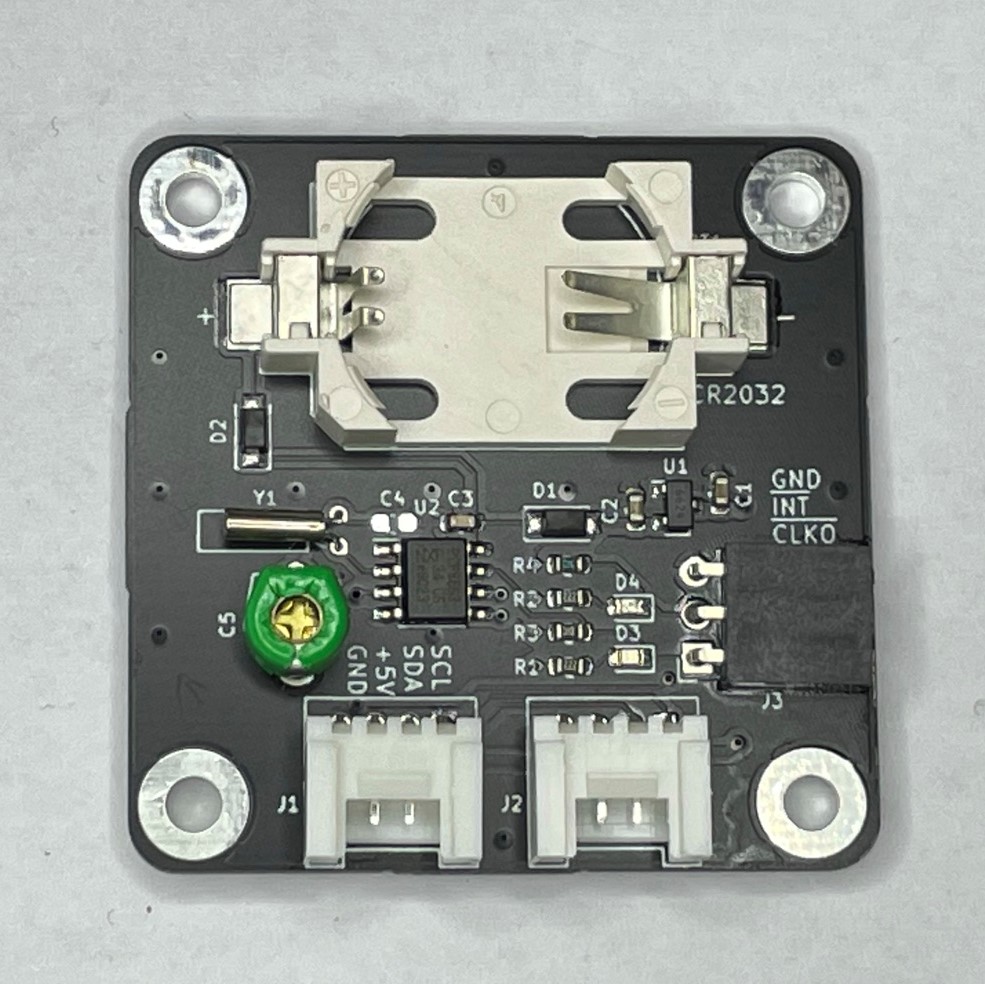
M5 シリーズ用に作成した RTC 基板です。水晶振動子 により高精度に時刻を刻みます。バッテリ・バックアップにより本体が電源オフの状態でも時刻を維持します。
M5 仕様の Grove コネクタ
M5 製品の Grove コネクタ仕様(電源 5V, 信号レベル 3.3V)に合致します。Grove コネクタが 2 個あり、I2C デバイスの数珠つなぎができます。
M5 製品と同仕様の RTC
M5Core2, M5StickC/C Plus, M5CoreInk, M5Paper, M5Camera/F/X に内蔵されている BM8563 と互換の RTC(PCF8563) を搭載し、M5 用の多くのソフトウェアを利用できます。
INT, CLKO 信号出力
PCF8563(BM8563) の INT 信号、CLKO 信号を、基板上のピンソケットから取り出せます。これらの信号は 3.3V に 10kΩ でプルアップしています。基板上の LED(INT: 赤、CLKO: 緑)で信号オンを確認できます。
時刻の精度を改善
基板上にトリマコンデンサを搭載し、時刻の精度を改善できます。出荷時には、以下の機器を用いて室温(15 - 25 ℃程度のどこか)にて調整済です。(※固定コンデンサ C4, トリマコンデンサ C5 はどちらか一方を実装します。トリマコンデンサを実装している場合、C4 には部品がありません。)
- 周波数カウンタ (1) を GPS 受信機 (2) の 1PPS 信号で校正
(1) 秋月電子通商「8桁周波数カウンターキット」 AE-FCOUNT3
(2) 秋月電子通商「GPS受信機キット~」 AE-GYSFDMAXB
- RTC 基板の CLKO から 1Hz 信号を取り出し、1PPS の代わりに入力
- 周波数カウンタの表示が所定の値に近づく様、RTC 基板上のトリマを調整
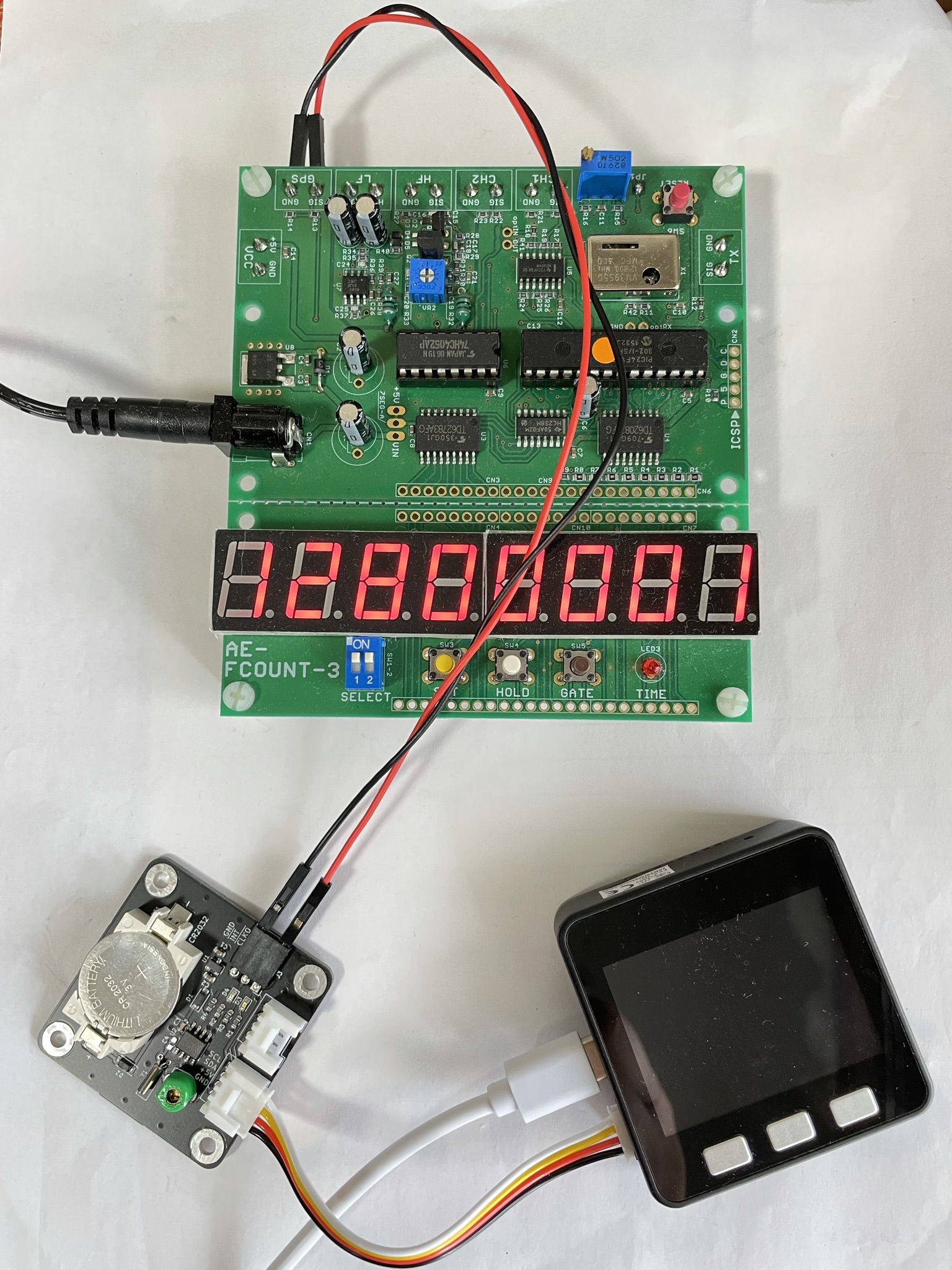
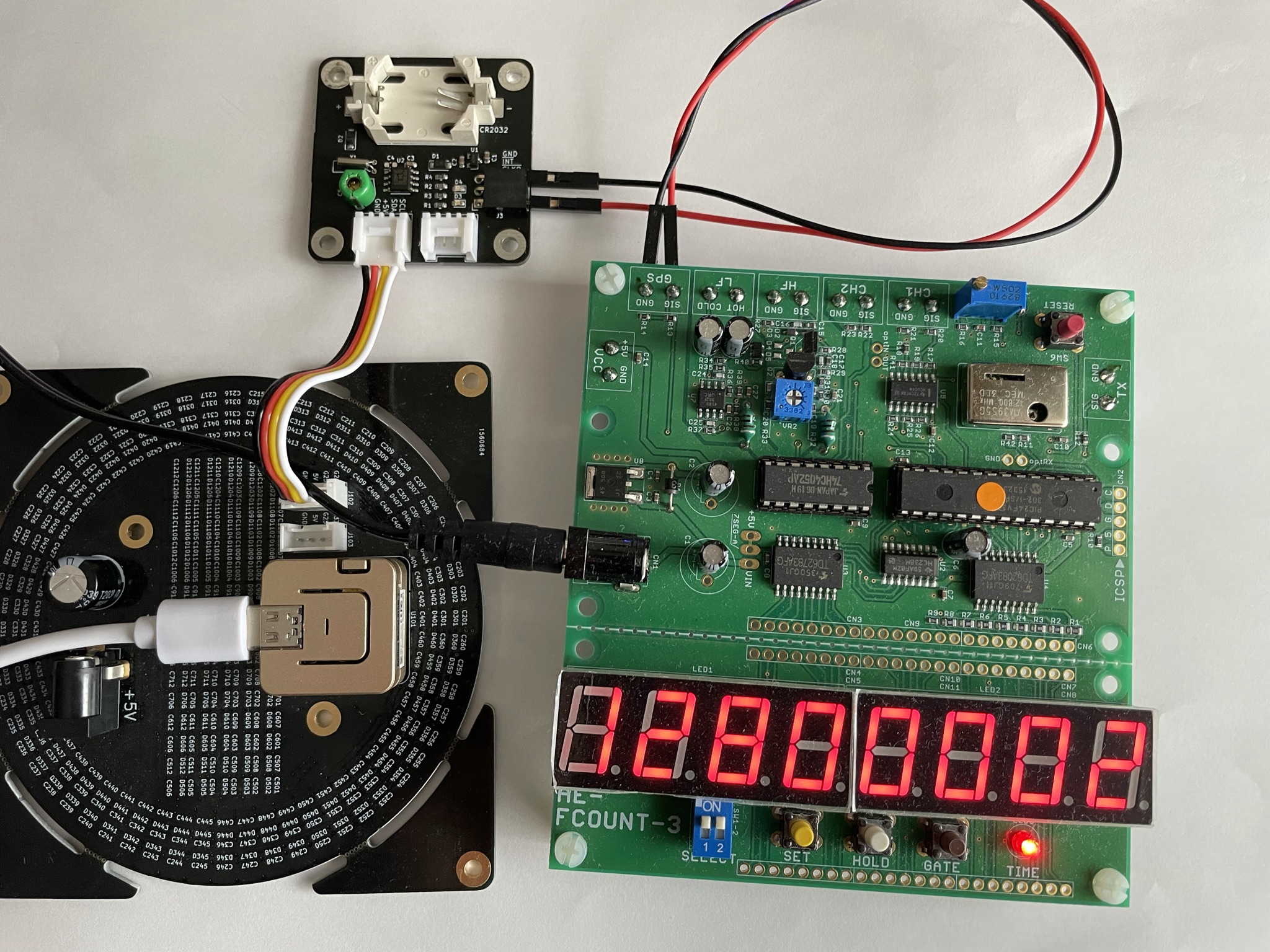
RTC の使用にあたっては、一般に入手可能なライブラリを利用することができます。
他の I2C デバイスとの共存や、NTP との相互補完を想定したサンプルプログラムを作成し、BF-027 フォルダに置きました。詳細な説明は Qiita(参考を参照)にあります。これらのプログラムは M5Stack 社の RTC ユニットでも使用できます。
BF_Pcf8563.h, BF_Pcf8563.cpp
RTC PCF8563(BM8563) にアクセスし、時刻、アラーム、タイマー、クロック出力などの機能を使用するためのドライバです。
BF_Pcf8563Test.h, BF_Pcf8563Test.cpp
上記 BF_Pcf8563.cpp の機能をテストするプログラムです。
BF_RtcxNtp.h, BF_RtcxNtp.cpp
RTC と NTP を相互補完的に使用するためのプログラムです。
BF-027.ino
上記プログラムの使用例です。
(1) Qiita 「M5Atom, M5Stack Core 用の I2C リアルタイムクロック基板を作って動かす」
(2) Qiita 「ESP32 において NTP の時刻同期を捕まえて RTC を更新する」
| Qty | Value | Footprint | References |
|---|---|---|---|
| 2 | 10k | Resistor_SMD:R_0603_1608Metric | R3, R4 |
| 2 | 1N4148 | Diode_SMD:D_SOD-123 | D1, D2 |
| 2 | 1u | Capacitor_SMD:C_0603_1608Metric | C1, C2 |
| 2 | 2.2k | Resistor_SMD:R_0603_1608Metric | R1, R2 |
| 2 | I2C | opl:HW4-2.0-90D | J1, J2 |
| 1 | 100n | Capacitor_SMD:C_0603_1608Metric | C3 |
| 1 | 15p | Capacitor_SMD:C_0603_1608Metric | C4 |
| 1 | 30p | bf:BF@TZ03-F | C5 |
| 1 | 32768Hz | bf:BF@Crystal_DS26_D2.0mm_L6.0mm_Horizontal | Y1 |
| 1 | CR2032 | bf:BF@QJ-BS-6 | BT1 |
| 1 | GREEN | LED_SMD:LED_0603_1608Metric | D3 |
| 1 | LOGO | bf:BF@logo5 | G*** |
| 1 | OUT | bf:BF@PinSocket_1x03_P2.54mm_Horizontal | J3 |
| 1 | PCF8563T | Package_SO:SOIC-8_3.9x4.9mm_P1.27mm | U2 |
| 1 | RED | LED_SMD:LED_0603_1608Metric | D4 |
| 1 | XC6206P332MR | Package_TO_SOT_SMD:SOT-23 | U1 |
The 21 most common of 25 parts.
It measures 44 × 44 mm and has 2 copper layers, 1.6 mm thick.
25 parts, built around the PCF8563T/5, XC6206P332MR and CR2032. The full list of its parts is on this page, with links to each part's symbol and footprint where PCBKit's library has them.
From the botanicfields/PCB-RTC-PCF8563-for-M5 repository on GitHub, at the commit this page was made from: the board is PCBV02L01/KiCad/bf-027.kicad_pcb. PCBKit opens the board in the browser, with nothing to install.
Its repository publishes it under the CC0-1.0 licence: you may reuse it on that licence's terms (keep the author's notice, and for a copyleft licence share your changes alike).
SuperPower/Artemis
All hardware designs and products you can find in this repository is licensed under CERN Open Hardware Licence Version 2 - Weakly Reciprocal


picafe/sensors-breakout
Breakout board for variety of useful sensors in a tiny footprint!

WestianPKl/pcb-docs
A collection of custom PCB designs created in KiCAD, centered around the Raspberry Pi Pico (RP2040) platform. Each board is a standalone module that connects to the Main Board and extends its functionality via I2C, SPI…

garrettsworkshop/TimeDisk
Apple II memory expansion card with 1 MB battery-backed RAM and NoSlotClock-compatible clock


TalismanDesign/PocketMage_PDA
An E-Ink PDA device using the ESP32 S3.
