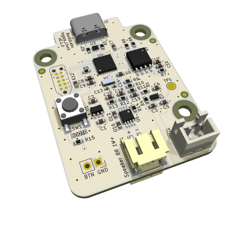
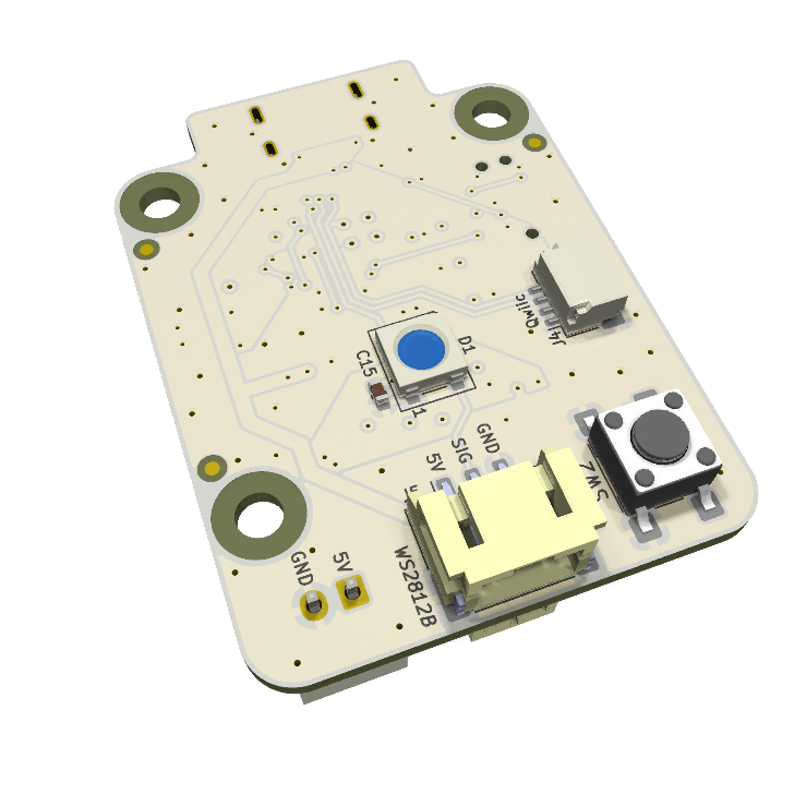
Hoppy clock is an open-source printed circuit board by borkdlabs, from the borkdlabs/hoppy_clock repository on GitHub, published under the MIT licence. It is a 4-layer board of 35 × 48 mm with 61 parts on 57 nets, routed with 342 tracks and 113 vias.
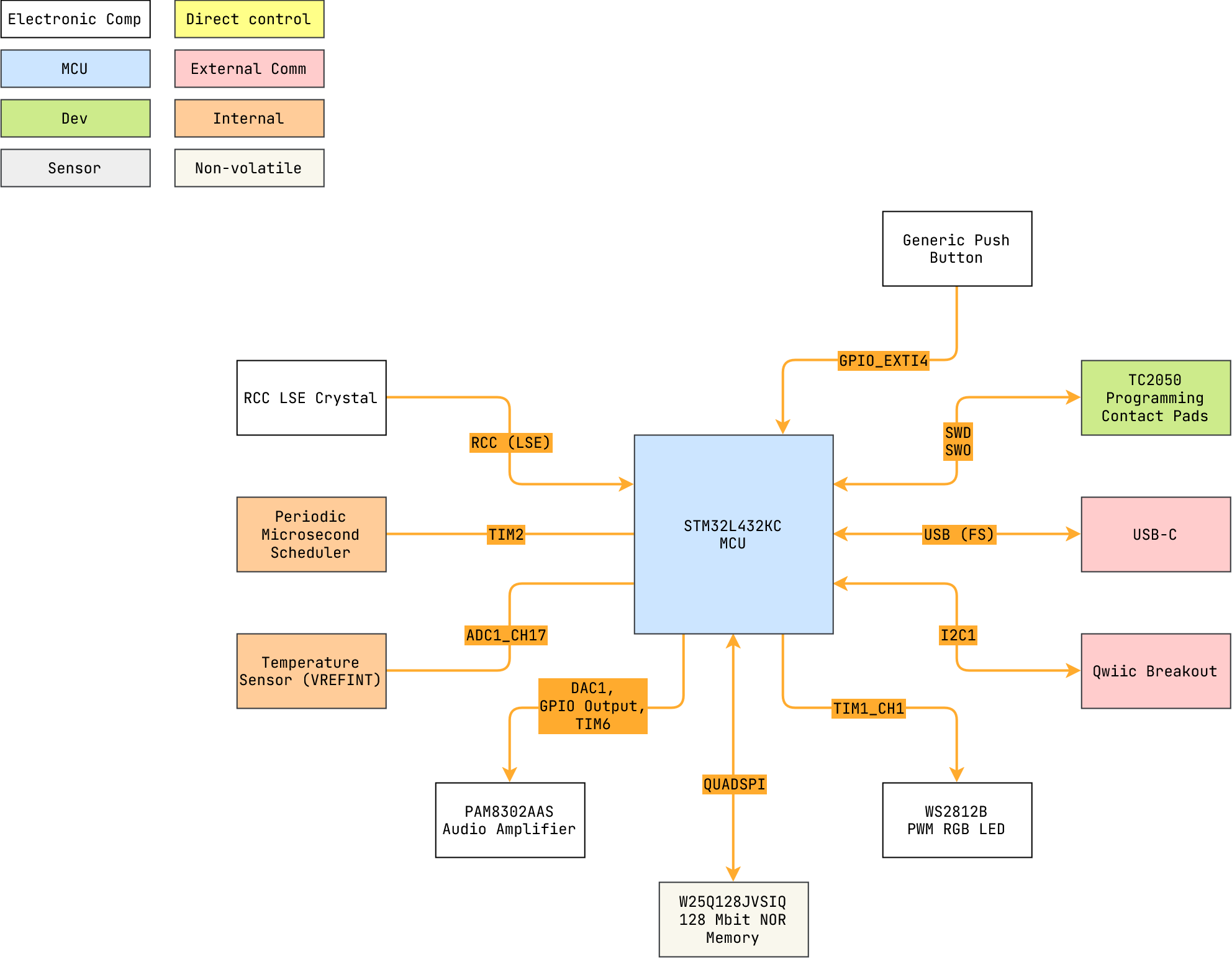
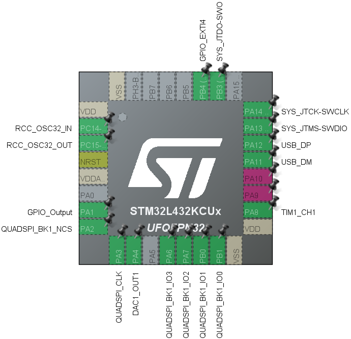
It is built around the STM32L432KCU6, PAM8302AASCR and W25Q128JVSIQ, with the TPS2116DRL, USBLC6-2P6 and ECS-.327-6-34R-C-TR among its other parts. Its parts include 20 capacitors, 15 resistors, 6 ICs, 6 connectors and 2 switches. It belongs with the lEDs and displays boards and the STM32 boards of this library.
⏰ Alarms: up to 64, each either weekly (any set of weekdays) or monthly (a
day of the month) at a chosen time. Every alarm has its own light look, sound,
volume fade-in and auto-quiet timeout.
💡 Lamp: the single button toggles a warm lamp look on/off, the "off"
state can settle to a dim ambient rather than fully dark.
✨ Lights: parametric looks (solid, rainbow, sweep, breathe,
wipe) rendered across the onboard LED and any chained via the
WS2812B breakout connector, every one of them with its own fade and optional
flicker.
🔊 Sounds: two slots, ~4 minutes each at the default 16 kHz (16-bit PCM,
sample rate is selectable up to 48 kHz), streamed from flash. Alarms play them
with an optional fade-in.
🔋 Low power: the MCU sleeps between events and drops into STOP2 once the
system is idle, waking on the next alarm or a button press (useful on backup
supply).
🖥️ Configuration: nothing is hard-coded, the board takes its settings over
USB from the web app (Chrome or
Edge, nothing to install).
🔴 Clock-unset cue: if the time has never been set (for example, after a
full power loss), the onboard LED (index 0) blinks dim red and alarms are
blocked from triggering until the clock is set.
User controllable hardware and/or firmware driven inputs.
Switch/Jumper
Ref
Description
BOOT0 button
SW1
Push to pull BOOT0 high
User button
SW2
Generic 6 mm SMD button with through-hole breakout
2.3 LEDs
LEDs used to show board status and/or user controllable.
LED
Mark
Description
WS2812B LED
None
RGB addressable LED
2.4 Test Pads
Test Point
Ref
Description
TPS2116 ST
TP1
ST pin from onboard TPS2116
2.5 Power Supply
By default, the board is powered from the USB-C 5 V source. An onboard TPS2116
priority power mux allows a backup 5 V supply to be connected via the
Backup supply connector (for example, a regulated battery pack output). If the
USB-C supply drops below the mux threshold, the TPS2116 automatically switches
the board over to the backup supply and switches back when USB-C power returns.
The mux status pin (ST) is exposed on the TPS2116 ST test pad and is pulled
low whenever the backup supply is in use, allowing a probe to detect the active
source during development/testing.
External LEDs on the WS2812B breakout connector are powered from USB (VBUS)
directly, not the priority power mux in order to prevent excessive battery drain
during a power outage. The single onboard LED is on the priority power mux
supply, so it remains available for minimum operation on battery power.
2.6 Speaker
An 8 ohm, >= 1 W speaker can be connected via the Speaker connector. The
amplifier output is bridge-tied (BTL): both terminals are driven, so neither may
be connected to ground.
3 Firmware
The firmware is fixed, all user settings (time, alarms, light looks, the lamp,
sounds and the LED count) live in the W25Q NOR flash and are written over USB at
runtime. Settings survive resets (the clock's time is kept in the STM32 backup
domain), as long as the board stays powered from USB-C or the backup supply. A
full power loss resets the clock (see the clock-unset cue above). A flash wipe
returns the unit to a clean state.
Stored settings carry a format version. A firmware update that changes that
format resets them: rather than misread an older image, the board falls back to
empty defaults, comes up on its built-in lamp look and needs reconfiguring.
3.1 User Button Controls
Action
While idle
While an alarm is ringing
Short press
Toggle the lamp on/off
(ignored)
Long press
Play / stop the button song
Silence the alarm
3.2 USB Configuration
The board enumerates as a USB CDC virtual serial port and speaks a small framed
command protocol (firmware/Core/Inc/usb_cmd.h). Two hosts implement it:
Both open the same serial port and only one program may hold it at a time.
Connecting: When the clock is idle and off USB it deep-sleeps (STOP2) and
deliberately presents as detached, so plugging into a host shows no device at
first. To connect:
Plug the USB-C cable into the host.
Press the button once to wake the clock. It re-attaches and enumerates as
a virtual serial port (the same short press also toggles the lamp as usual,
harmless).
Run the Python tool.
If the clock is already awake (in use, ringing, an alarm just fired, or the lamp
is showing a continuously animating look), it enumerates the moment you plug in,
with no press needed. Unplugging or the host going to sleep allows the system to
return to deep sleep.
Why a button press? The clock cannot tell a data host (a PC) from a plain
USB-C charger or power bank, both simply present 5 V with no reliable way to
distinguish them until an enumeration that only a real host answers. Waking
and enumerating on every plug-in would spend energy for the majority of the
time the port is used only to charge or power the unit and risks staying awake
on a battery pack it mistook for a host. Gating USB behind a deliberate button
press ties enumeration to a real intent to configure and lets the clock stay
in its lowest-power state whenever it is merely being powered. Firmware itself
is flashed over SWD (the TC2050 header), independent of this path.
A single static page that drives the port through the
Web Serial API,
so there is nothing to install beyond the OS's own CDC driver. It needs Chrome
or Edge on desktop (Windows, macOS or Linux); Firefox, Safari and mobile
browsers do not implement Web Serial and the page says so rather than
half-working.
Press Connect and pick the STM32 virtual COM port (0483:5740). Permission is
granted per site and remembered, so later visits reopen that port on their own.
3.2.2 Python Tool
bash
cd software
python main.py <command> [options]# add -p COM7 (or /dev/ttyACM0) to pick the port
Needs Python 3 with pyserial (pip install -r software/requirements.txt),
MP3 uploads additionally need ffmpeg on the PATH. See top docstring in
main.py for more information.
Command
Description
set-time
Sync the RTC to the host's local time
add-alarm / set-alarm
Add an alarm (e.g. --at 08:00 --days weekdays) / replace all with one
remove-alarm N / clear-alarms
Delete one alarm by index / delete all
list-alarms
Show alarms, lights, the lamp and LED count
set-light
Define a light look (--effect, --fade, --curve, --flicker)
set-lamp
Choose the on/off lamp idle looks
set-led-count N
Set the number of chained LEDs
upload-sound
Store a sound from a WAV/MP3 file or a synthesized tone
play-sound / stop-sound
Play / stop a stored sound now
set-button-song
Set which sound the long-press plays
wipe
Factory-reset the flash (--full also scrubs the audio)
Run python main.py --help (or <command> --help) for the full option list.
3.3 Light Looks
A light look is not a stored animation but a handful of parameters the firmware
renders live across the whole chain. Up to 16 are stored; alarms and the two
lamp idle states each reference one by id. Every look sets a base colour and a
master brightness, then picks an effect:
Effect
Renders
Period
Spread
solid
The whole strip held at one colour
-
-
rainbow
The HSV hue wheel, cycling
Time per turn
Hue step per LED (0 = strip as one colour)
sweep
A lit band travelling over darkness
Time per pass
Band width, in LEDs
breathe
The colour swelling and receding
Time per breath
-
wipe
The colour painted along from LED 0
Time to cross
Width of the soft front, in LEDs
wipe-reverse
The same, from the far end of the chain
Time to cross
Width of the soft front, in LEDs
solid settles and holds as an idle. rainbow, sweep and breathe loop
until something else is played.
The two wipes run once and then hold, like a solid that arrives along the
strip instead of everywhere at once. Each LED blends from whatever it was
showing when the wipe started, so over a dark strip it fills the strip up LED by
LED, and over another look it paints the new colour across the old one. With
three LEDs and a one-LED front, their levels step through 0 0 0,
128 0 0, 255 0 0, 255 128 0 and on to 255 255 255. A wider spread lets
several LEDs ramp at once for a smoother edge. Because the wipe is already a
transition, it is usually paired with a fade of 0; a lamp-off look of
wipe-reverse at brightness 0 then rolls the light back down the strip.
The same three settings apply to all six alike:
Setting
Does
fade
Time this look takes to fade in over whatever is already lit
curve
Shape of that fade: linear (constant rate) or ease (gentle at both ends)
flicker
Amplitude of a random brightness dip, redrawn several times a second
A fade runs on entry only. Every transition uses the fade of the look
arriving, never of the one leaving: playing a look is the only thing that starts
a fade, and by then the previous look is already on its way out. So the fade
on a rainbow decides how that rainbow appears and has no say in what happens
when something later replaces it.
To fade a look both in and out, set the fade on that look and on whatever
replaces it. A lamp that eases up and back down over two and a half seconds:
Look
Effect
Brightness
Fade
Curve
Lamp on
rainbow
200
2500
ease
Lamp off
solid
0
2500
ease
Give the lamp-off look a fade of 0 instead, and it cuts to black the instant the
button is pressed, no matter how long the rainbow's own fade is. A fade of 0
always means "no fade, show this look now".
The look being faded away from is held as a still frame, so a rainbow stops
cycling the moment it is replaced and dims from whichever hues it had reached.
Flicker is a texture rather than a shape, so it is set separately from the
curve, and the two combine freely. Unlike the fade it never ends, which is what
makes a solid warm white read as a candle instead of a lamp.
A continuously animating look keeps the board out of deep sleep. Only a
solid look or a wipe, with flicker 0, ever finishes: once its fade lands
(and a wipe has crossed the strip), it settles on a fixed colour, stops
rendering and lets the MCU drop into STOP2. rainbow, sweep and breathe
loop for as long as they are showing, and any flicker above 0 never stops, so
a look of either kind holds the board in light sleep instead. Two consequences
follow:
Power. Light sleep gates the core but keeps the clocks and peripherals
live, so the board sits at run current rather than the microamps STOP2 draws.
That matters most on the backup supply, where a permanently animated lamp look
is a far heavier load than a settled solid one.
USB. A board that never deep-sleeps never detaches either, so it
enumerates the moment it is plugged in with no button press needed (see
3.2 USB Configuration). Parking the lamp on an
animated look is a way to keep it permanently connectable while configuring.
The clock-unset warning blink holds the board awake in the same way, until the
time is set.
3.4 Sounds
Two slots hold one sound each, 7.5 MiB apiece, in the same NOR flash as the
settings. Alarms reference a slot by id, and the long press plays one.
The source file's own format does not matter. Uploading anything that is not
already raw PCM runs it through ffmpeg, which decodes and resamples it to mono
at the rate and sample format you pick:
bash
ffmpeg -i song.mp3 -ac 1 -ar <rate> -f s16le|u8 -
A 320 kbps 44.1 kHz stereo MP3 and a 96 kbps mono one land on the board as the
same shape of data, so there is nothing to read off a file to decide with. What
gets stored is the raw blob plus the rate and format it was made at, the
firmware reads those back at playtime and clocks the DAC accordingly.
So the two settings are a trade between quality and how much fits in a slot:
Rate
s16 (2 B/sample)
u8 (1 B/sample)
8000
8m 11s
16m 23s
16000 (default)
4m 05s
8m 11s
22050
2m 58s
5m 56s
32000
2m 02s
4m 05s
48000 (max)
1m 21s
2m 43s
Two things to weigh:
The speaker is the real ceiling. Output is a 12-bit DAC into a PAM8302A
driving a little speaker, so 16 kHz already covers about as much bandwidth as
it can reproduce. Higher rates mostly spend slot space on detail that never
reaches the air.
u8 halves the size but adds hiss. Eight-bit quantization is audible on
anything sustained. It suits short effects and tones, not music.
In practice leave both on their defaults (s16 at 16000 Hz) and use the trim
option to fit a long track, rather than dropping quality to make it fit. Reach
for u8 or a lower rate only when a long clip matters more than how it sounds.
3.5 Firmware Update (DFU)
This flashes new firmware (not settings, those use the USB tool above).
Normally firmware is programmed over SWD (the TC2050 header). Without a
debugger, the STM32L432's built-in USB bootloader (DFU) flashes it over the same
USB-C port.
BOOT0 is sampled only at power-up, so DFU has to be entered on a fresh cold
boot with the button held:
Remove all power, unplug USB and anything on the Backup supply
connector. A backup supply keeps the MCU running, so plugging in USB would
not be a cold boot and BOOT0 would never be re-sampled. (With no backup
supply attached, USB is the only source and this is automatic.)
Hold the BOOT0 button.
While still holding it, connect USB-C to the computer. The board powers up
into the bootloader and enumerates as STM32 BOOTLOADER (DFU, USB
0483:DF11). Release the BOOT0 button.
Flash the image to the flash base 0x08000000, then restart into it with
your DFU tool/software.
4 Development
4.1 Web App
webapp/ is plain ES modules with no build step, no bundler and no
dependencies, it is served exactly as it sits in the repository. Web Serial only
runs in a secure context and http://localhost counts as one, so a static
server is enough and no HTTPS setup is needed:
Framing and CRC-8, mirrors firmware/Core/Inc/usb_cmd.h
dev/
The helpers below, stripped from the published site
Working without a board. The offline checks exercise the framing and
transaction layers against a fake CDC port, covering the happy path, error
statuses, command timeouts and a mid-command unplug:
bash
cd webapp/dev
node test-device.mjs
For the UI itself, paste
dev/inject-fake-port.js into the browser
console with the page open. It stubs navigator.serial.requestPort with a clock
whose RTC runs 47 s fast, so the connect flow, the drift readout and the sync
button can all be driven dry. More in webapp/dev/.
A protocol change touches three implementations, keep them in step:
firmware/Core/Inc/usb_cmd.h, software/main.py and webapp/js/
(protocol.js for the framing, alarms.js, lights.js and sounds.js for the
record layouts).
4.2 Deployment
.github/workflows/pages.yaml publishes the app
to GitHub Pages on every push to main touching webapp/. It runs
node --check over each module and the offline checks above, copies webapp/
to the site root minus dev/, then deploys. Pull requests build and test but do
not publish and the workflow can also be started by hand (Actions -> Pages ->
Run workflow).
The repository's Pages source must be set to GitHub Actions
(Settings -> Pages -> Build and deployment -> Source).
Acknowledgements
This project is sponsored by PCBWay, whose PCB
manufacturing services are essential in producing high-quality prototypes for
its development. Their support ensures reliable boards that meet the project's
demands.
Why PCBWay?
PCBWay stands out for their exceptional services and commitment to the
community:
PCB manufacturing: multilayer, rigid-flex and other advanced fabrication.
PCB assembly: soldering, component sourcing and assembly.
Other services: CNC machining and 3D printing, for projects that need more
than a board.
Fast turnaround: quick production times that keep a project on schedule.
Open source and education: they sponsor projects and publish tutorials,
videos and documentation for developers and hobbyists.
This commitment to education and open-source advocacy was a key factor in
choosing them as a partner 🙂.
Their dedication to professional-grade services and fostering innovation makes
PCBWay an invaluable partner in bringing this project to life.
Third-Party Licenses
This project uses the following open-source software components:
It measures 35 × 48 mm and has 4 copper layers, 1.56 mm thick.
What parts does the Hoppy clock use?
61 parts, built around the STM32L432KCU6, PAM8302AASCR, W25Q128JVSIQ and TPS2116DRL. The full list of its parts is on this page, with links to each part's symbol and footprint where PCBKit's library has them.
Where can I download the Hoppy clock KiCad files?
From the borkdlabs/hoppy_clock repository on GitHub, at the commit this page was made from: the board is hardware/hoppy_clock.kicad_pcb and its schematic hardware/hoppy_clock.kicad_sch. PCBKit opens the board in the browser, with nothing to install.
Can I use the Hoppy clock design in my own project?
Its repository publishes it under the MIT licence: you may reuse it on that licence's terms (keep the author's notice, and for a copyleft licence share your changes alike).
The Bounded Infrared Recording Drone Ecosystem (BIRD-E) is a tethered quadcopter with an attached infrared camera, with livestream functionality and XBOX ground control. Senior design capstone at Purdue ECE.