Skip to the content
PCBKitNew board
2 layers148 × 90 mmClock v2, the printed circuit board in 3D

Nixie tube clock

Size
148 × 90 mm
Copper layers
2
Thickness
1.6 mm
Parts
230
Nets
280
Pads
831
Tracks, vias
1,257, 207
Pours
21
Routed
Yes
KiCad
KiCad 10.0 (file 20260206)
Created
13 Apr 2026
Updated
19 May 2026

Overview

Clock v2 is an open-source printed circuit board by bonnetn, from the bonnetn/nixie_clock repository on GitHub. It is a 2-layer board of 148 × 90 mm with 230 parts on 280 nets, routed with 1,257 tracks and 207 vias.

It is built around the 74HC595, MMBTA42 and AO3401A, with the MMBT3904, SMAJ5.0A and SS54 among its other parts. Its parts include 115 resistors, 62 transistors, 13 capacitors, 8 ICs and 5 connectors. It belongs with the lEDs and displays boards of this library.

Main components

6

README

README.md

Nixie Tube Clock

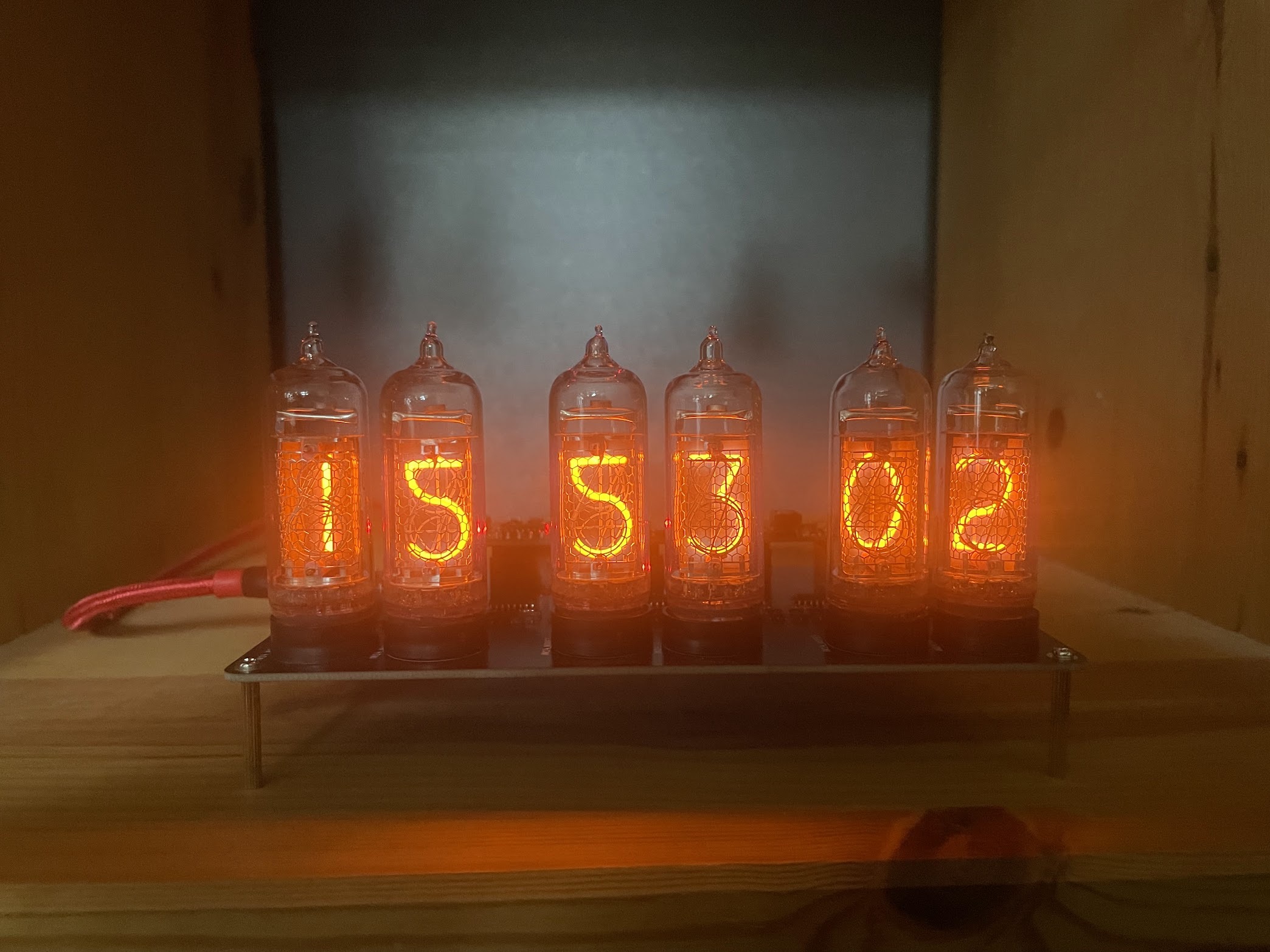
A custom Nixie tube clock built on an ESP32, written in Rust using the Embassy async framework.

Clock showing time

Hardware

  • Microcontroller: ESP32
  • Display: 6 × IN-14 Nixie tubes
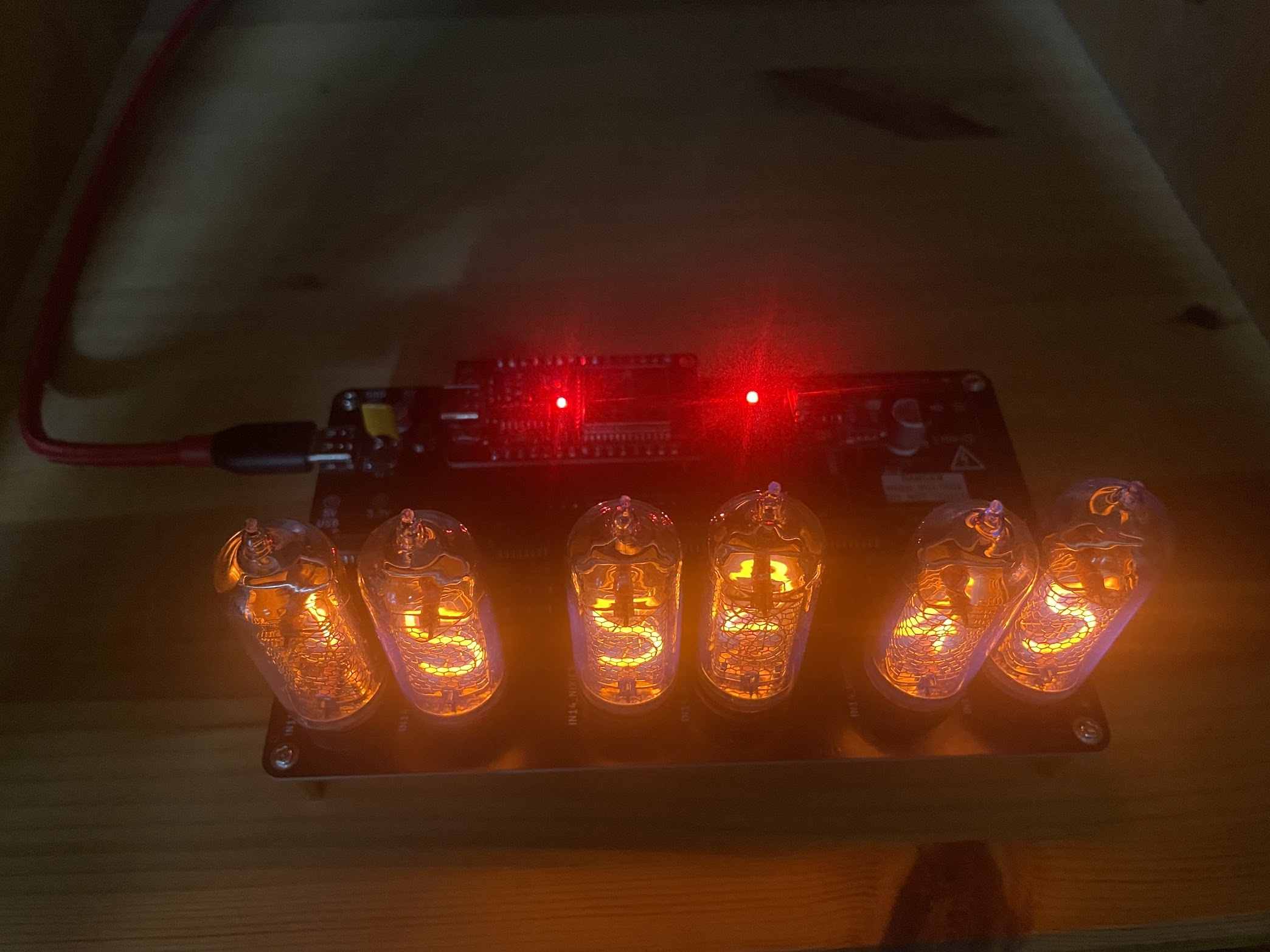
  • Driver: 8 × 8-bit shift registers (74HC595) controlling each tube's cathodes
  • Power: High-voltage supply (170 V DC) switched by a high-side transistor
  • Storage: On-chip flash for timezone data persistence

PCB top view

Features

  • NTP time sync — polls nl.pool.ntp.org periodically and maintains an epoch offset
  • Timezone awareness — fetches IANA TZif data over HTTP and persists it to flash; handles DST transitions
  • Cathode poisoning prevention — every 15 minutes, each digit on every tube is lit for a calculated duration proportional to how little it has been used
  • Power window — HV supply is on only between 09:00 and 23:00 local time; the ESP deep-sleeps outside that window
  • Presence detection — polls a local presence server; deep-sleeps for 5 minutes when nobody is home
  • OTA updates — accepts firmware uploads over a TCP server on the local network

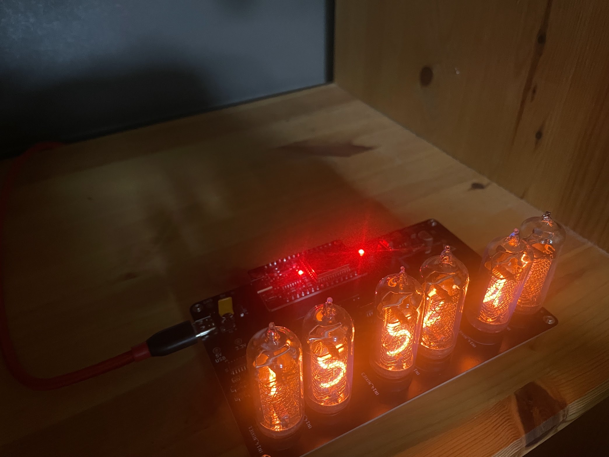
Clock from above at an angle

Repository layout

text
code/
  clock_v2_core/   # no_std library: time, NTP, TZif, cathode-poisoning logic
  firmware/        # ESP32 binary: Embassy tasks, GPIO, network, flash
kicad/             # PCB schematic and layout
ansible/           # Router setup playbook

Building & flashing

bash
# Host unit tests (fast, no hardware needed)
cargo test -p clock_v2_core

# Flash to device (requires ESP32 toolchain and probe)
cd code/firmware
DEFMT_LOG=debug cargo run --release

Secrets (wifi_ssid.txt, wifi_password.txt) are compiled in from plain-text files in code/firmware/ — create them before building.

Parts

230
QtyValueFootprintReferences
721MΩPCM_JLCPCB:R_0402R14, R15, R16, R17, R18, R19, R20, R21, R22, R23, R24, R25, R27, R28, R29, R30 +56
60MMBTA42Package_TO_SOT_SMD:SOT-23Q10, Q11, Q12, Q13, Q14, Q15, Q16, Q17, Q18, Q19, Q20, Q21, Q22, Q23, Q24, Q25 +44
1510kΩPCM_JLCPCB:R_0603x4R101, R102, R103, R104, R105, R106, R107, R108, R109, R110, R111, R113, R114, R115, R116
1233ΩPCM_JLCPCB:R_0402R2, R3, R4, R5, R6, R7, R8, R9, R10, R11, R12, R13
10100nFPCM_JLCPCB:C_0402C1, C4, C6, C7, C8, C9, C10, C11, C12, C13
874HC595Package_SO:SOIC-16_3.9x9.9mm_P1.27mmU1, U2, U3, U4, U5, U6, U7, U8
7TestPointTestPoint:TestPoint_Loop_D2.50mm_Drill1.0mmTP1, TP2, TP3, TP4, TP5, TP6, TP7
610kΩPCM_JLCPCB:R_0603R26, R39, R52, R65, R78, R91
6~nixies-us:nixies-us-IN-14IN14_NIXIE1, IN14_NIXIE2, IN14_NIXIE3, IN14_NIXIE4, IN14_NIXIE5, IN14_NIXIE6
4MountingHole_PadMountingHole:MountingHole_2.5mm_Pad_TopBottomH1, H2, H3, H4
3220kΩPCM_JLCPCB:R_0402R92, R93, R94
3FiducialFiducial:Fiducial_1mm_Mask2mmFID1, FID2, FID3
2100kΩPCM_JLCPCB:R_1206R96, R97
247uFCapacitor_SMD:CP_Elec_5x5.4C2, C5
25.1kΩPCM_JLCPCB:R_0402R99, R100
2Conn_01x15Connector_PinHeader_2.54mm:PinHeader_1x15_P2.54mm_VerticalJ1, J2
2LOGOcustom_lib:hv_backG***, G***
11.2kΩPCM_JLCPCB:R_0402R95
11MΩPCM_JLCPCB:R_1206R98
14.7uFCapacitor_SMD:CP_Elec_8x10.5C3
147kΩPCM_JLCPCB:R_0402R1
1AO3401APCM_JLCPCB:Q_SOT-23Q2
1Conn_01x04Connector_PinHeader_2.54mm:PinHeader_1x04_P2.54mm_VerticalJ3
1Conn_01x06Connector_PinHeader_2.54mm:PinHeader_1x06_P2.54mm_VerticalJ4
1Connector, USB-TYPE-C-16PPCM_JLCPCB:TYPE-C-SMD_HX-TYPE-C-16PINJ5
1LEDPCM_JLCPCB:D_0805D1
1LOGOcustom_lib:hvG***
1MMBT3904Package_TO_SOT_SMD:SOT-23Q1
1PolyfuseCapacitor_THT:C_Disc_D5.1mm_W3.2mm_P5.00mmF1
1SMAJ5.0APCM_JLCPCB:D_SMAD2
1SS54PCM_JLCPCB:D_SMAD3

Questions

How big is the Clock v2 PCB?

It measures 148 × 90 mm and has 2 copper layers, 1.6 mm thick.

What parts does the Clock v2 use?

230 parts, built around the 74HC595, MMBTA42, AO3401A and MMBT3904. The full list of its parts is on this page, with links to each part's symbol and footprint where PCBKit's library has them.

Where can I download the Clock v2 KiCad files?

From the bonnetn/nixie_clock repository on GitHub, at the commit this page was made from: the board is kicad/clock_v2.kicad_pcb and its schematic kicad/8_low_side_switches.kicad_sch. PCBKit opens the board in the browser, with nothing to install.

Can I use the Clock v2 design in my own project?

Its repository states no licence, so its author keeps all rights: ask bonnetn before reusing the design.

Similar boards

  • 4 layers100 × 100 mmPhmod, the printed circuit board in 3D

    Phmod

    gallicchio/AMOD-and-RFMOD

    The tutorial's 2x12 adapter (/mudd/133electronics/icepi-zero-dac-adc/adapterboard/) with a 2 x 6 right-angle Pmod socket on a 15 mm extension of its right-hand end, so an Icepi Zero can drive AMOD-A's and RF-MOD's Pmod…

    234 parts
  • 2 layers100 × 110 mmKicad control board smt, the printed circuit board in 3D

    Kicad control board smt

    matthewcieplak/super-sixteen

    Code and schematics for the Super Sixteen Eurorack sequencer

    97 parts171
  • 2 layers121 × 75.5 mmJlctest, the printed circuit board in 3D

    Jlctest

    cjheath/jlcbasic

    JLC Basic parts library for Kicad fetched and converted from EasyEDA

    46 parts5
  • 4 layers99 × 60 mmGrip strength meter, the printed circuit board in 3D

    Grip strength meter

    houseofbigseals/grip_strength_meter_pcb

    schematic and pcb for custom esp32 grip strength meter project

    123 parts
  • 4 layers114.1 × 100.2 mmPanelised, the printed circuit board in 3D

    Panelised

    pnn69/Kicad_PCB

    Schematics and PCB's designed with Kicad

    252 parts
  • 4 layers194 × 40 mmRobobouoy V4.0, the printed circuit board in 3D

    Robobouoy V4.0

    pnn69/NicE-Buoy

    This device sails autonome to a given location.

    258 parts
  • 4 layers140 × 100 mmDc usv, the printed circuit board in 3D

    Dc usv

    TobleMiner/DC-UPS

    A small DC UPS, designed to keep small appliances like consumer network equipment running during power outages

    351 parts223CERN-OHL-P-2.0