4 layers152.4 × 63.5 mm
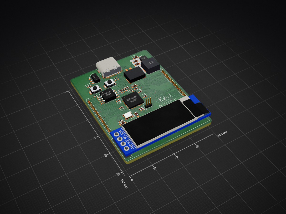
 bobis1/devboard
I made this project because I wanted some experience working with devboards before I start something more complex. I also wanted to make something where a microcontroller was on a devboard already.
Devboard is an open-source printed circuit board by bobis1, from the bobis1/devboard repository on GitHub. It is a 2-layer board of 39.3 × 51.7 mm with 45 parts on 61 nets, routed with 1,046 tracks and 62 vias.
It is built around the RP2040, W25Q128JVSIQ and TPS63000DRC. Its parts include 21 capacitors, 8 resistors, 5 ICs, 4 connectors and 2 switches. It belongs with the microcontroller boards boards and the RP2040 boards of this library.


A devboard with an inbuilt screen and a software platform that should help beginners learn the basics of computer science. This is a rp2040 devboard at it's core.
I made this project because I wanted some experience working with devboards before I start something more complex. I also wanted to make something where a microcontroller was on a devboard already.
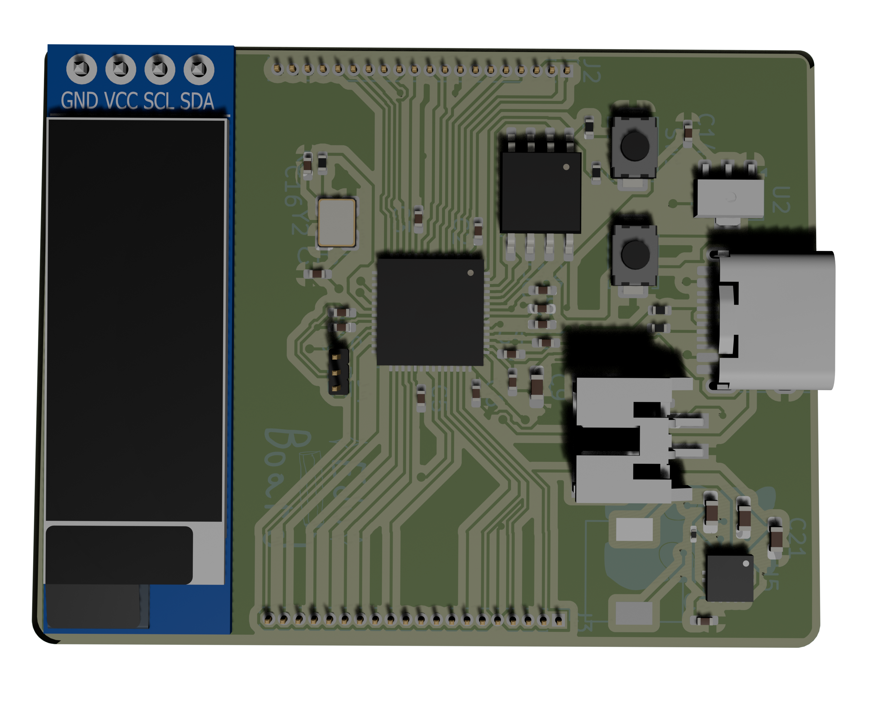
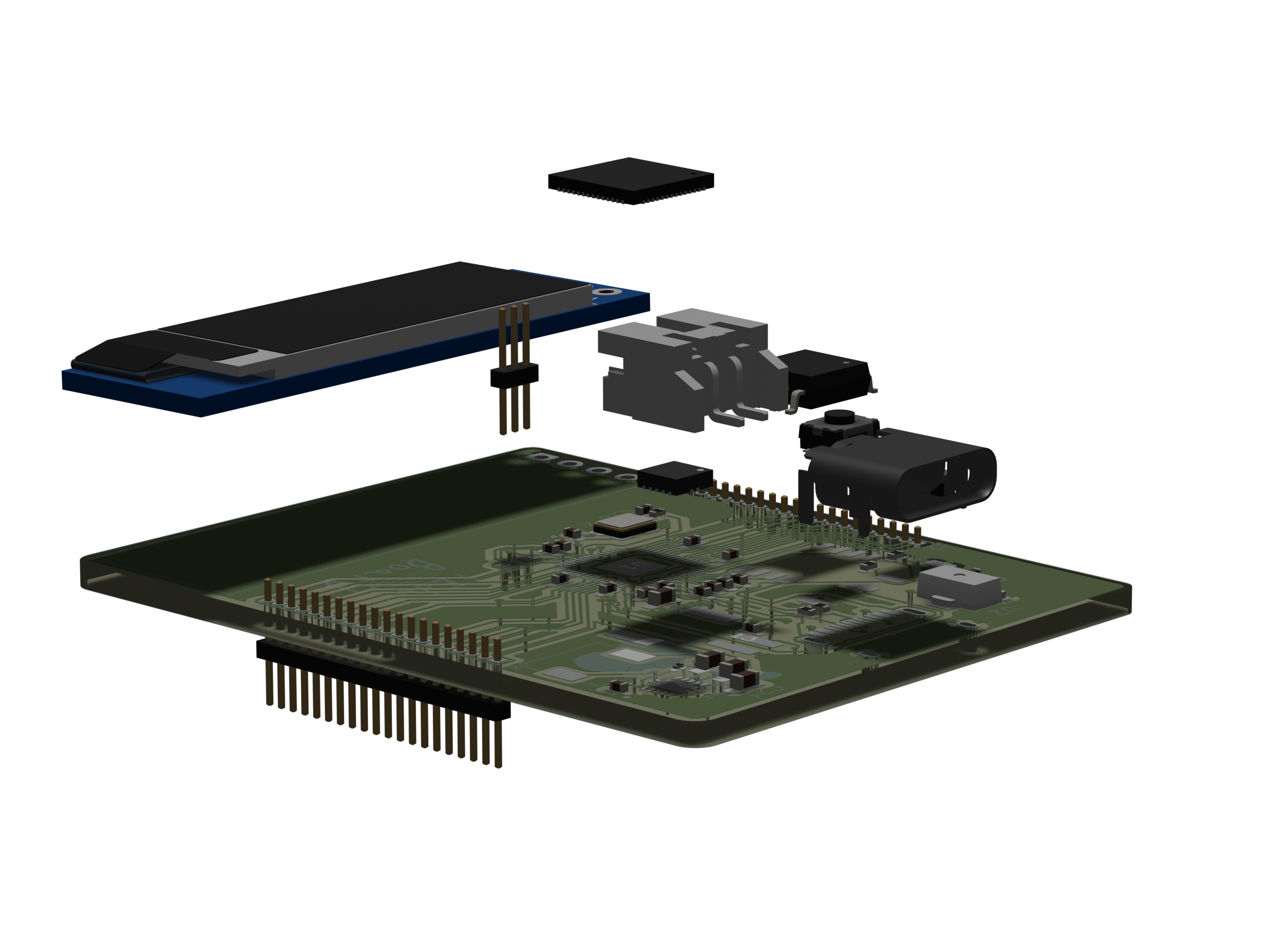 Above are renders made in blender.
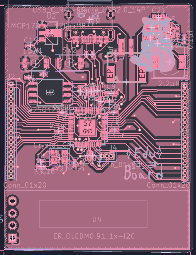

The assembly of the devboard is relatively straight forward. The first thing you need to do is you need to get a hotplate and some soder paste to carefully soder on all the SMD components onto the pcb(This will be new to me as I have never done it before). Then you need to soder on the header pins onto the pcb by placing your sodering iron on the joint between the pcb and the pin and putting solder into that joint.
The flashing of this works the same way as a normal raspberry pi pico. You need to hold down SW_1 to start the flashing process.
This BOM is for non PCBA. To be clear, I plan on using the bill of materials labeled BOM, BOM-PCBA is a BOM if you want to PCBA part of it.
| Qty | Value | Footprint | References |
|---|---|---|---|
| 11 | 0.1uf | Capacitor_SMD:C_0402_1005Metric_Pad0.74x0.62mm_HandSolder | C1, C2, C3, C4, C5, C6, C7, C8, C10, C11, C17 |
| 3 | 10μf | Capacitor_SMD:C_0603_1608Metric_Pad1.08x0.95mm_HandSolder | C18, C20, C21 |
| 2 | 10uf | Capacitor_SMD:C_0402_1005Metric_Pad0.74x0.62mm_HandSolder | C13, C14 |
| 2 | 27Ω | Resistor_SMD:R_0402_1005Metric | R3, R4 |
| 2 | 33uf | Capacitor_SMD:C_0603_1608Metric_Pad1.08x0.95mm_HandSolder | C15, C16 |
| 2 | 5.1KΩ | Resistor_SMD:R_0402_1005Metric | R1, R2 |
| 2 | Conn_01x20 | Connector_PinHeader_1.00mm:PinHeader_1x20_P1.00mm_Vertical | J2, J3 |
| 2 | SW_Push | Button_Switch_SMD:SW_SPST_TS-1088-xR020 | SW1, SW2 |
| 1 | 0.1μf | Capacitor_SMD:C_0402_1005Metric_Pad0.74x0.62mm_HandSolder | C19 |
| 1 | 100Ω | Resistor_SMD:R_0201_0603Metric | R8 |
| 1 | 10KΩ | Resistor_SMD:R_0402_1005Metric | R7 |
| 1 | 1K | Resistor_SMD:R_0402_1005Metric | R5 |
| 1 | 1KΩ | Resistor_SMD:R_0402_1005Metric | R6 |
| 1 | 1uf | Capacitor_SMD:C_0603_1608Metric_Pad1.08x0.95mm_HandSolder | C9 |
| 1 | 1uf | Capacitor_SMD:C_0402_1005Metric_Pad0.74x0.62mm_HandSolder | C12 |
| 1 | 2.2μH | Inductor_SMD:L_6.3x6.3_H3 | L1 |
| 1 | Conn_01x03 | Connector_PinHeader_1.00mm:PinHeader_1x03_P1.00mm_Vertical | J4 |
| 1 | Crystal_GND24 | Crystal:Crystal_SMD_3225-4Pin_3.2x2.5mm | Y2 |
| 1 | ER_OLEDM0.91_1x-I2C | Display:ER_OLEDM0.91_1x-I2C | U4 |
| 1 | LOGO | DevboardArt:SoupSmall | G*** |
| 1 | LOGO | DevboardArt:Sparkle | G*** |
| 1 | MCP1700x-120xxMB | Package_TO_SOT_SMD:SOT-89-3 | U2 |
| 1 | RP2040 | Package_DFN_QFN:QFN-56-1EP_7x7mm_P0.4mm_EP3.2x3.2mm | U1 |
| 1 | TPS63000 | Package_SON:Texas_DRC0010J_ThermalVias | U5 |
| 1 | USB_C_Receptacle_USB2.0_14P | Connector_USB:USB_C_Receptacle_HRO_TYPE-C-31-M-12 | J1 |
| 1 | W25Q128JVS | Package_SO:SOIC-8_5.3x5.3mm_P1.27mm | U3 |
| 1 | ~ | JST-PH-2.:JST-PH-2 | XT1 |
It measures 39.3 × 51.7 mm and has 2 copper layers, 1.6 mm thick.
45 parts, built around the RP2040, W25Q128JVSIQ and TPS63000DRC. The full list of its parts is on this page, with links to each part's symbol and footprint where PCBKit's library has them.
From the bobis1/devboard repository on GitHub, at the commit this page was made from: the board is Devboard-PCB/Devboard.kicad_pcb and its schematic Devboard-PCB/Devboard.kicad_sch. PCBKit opens the board in the browser, with nothing to install.
Its repository states no licence, so its author keeps all rights: ask bobis1 before reusing the design.


slintak/NPR70
The New Packet Radio on 70 cm band. Based on the project NPR from F4HDK.

richardclli/DIY-PL18-InternalMPM
An internal MPM (Multi-Protocol Module) for PL18 Mod

nicolaeandreivasile/bike-embedded-app
Embedded application for bikes that collect and display various riding data.


awetzelkern/CASE
Miminal flight computer designed to be a stepping-stone into creating PCB hardware and software for a fully custom thrust-vectored rocket.
