2 layers65.3 × 99.4 mm
Screen
benanderman/spork-8
An 8-bit CPU, made with TTL chips on custom, modular PCBs. Includes board designs, and Arduino code to program its instruction set and programs.
460 parts61MIT

 benanderman/spork-861
An 8-bit CPU, made with TTL chips on custom, modular PCBs. Includes board designs, and Arduino code to program its instruction set and programs.
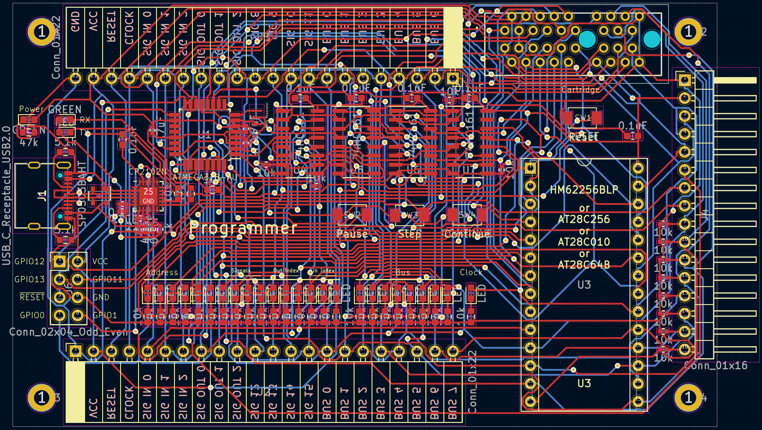
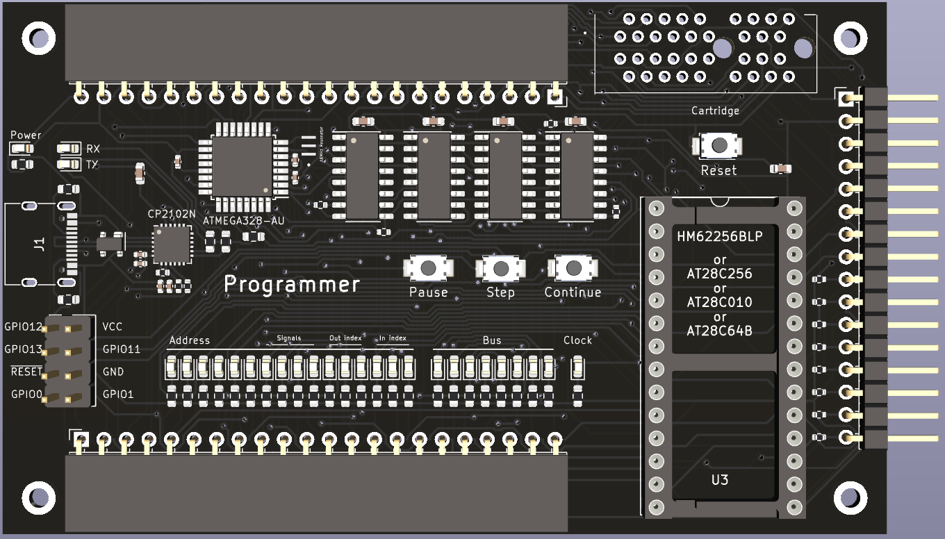
Programmer is an open-source printed circuit board by benanderman, from the benanderman/spork-8 repository on GitHub, published under the MIT licence. It is a 2-layer board of 99.6 × 59.9 mm with 110 parts on 99 nets, routed with 2,405 tracks and 207 vias.
It is built around the ATMEGA328-AU, 74HC161S and HM62256BLP-7, with the 3183-10200P1T and SP0503BAHTG among its other parts. Its parts include 46 resistors, 29 diodes, 13 capacitors, 7 ICs and 6 connectors. It belongs with the retro computing and games and interfaces and adapters boards and the AVR (ATmega, ATtiny) boards of this library.


This is an 8-bit computer project, inspired by Ben Eater's 8-bit breadboard computer. It's made out of modular PCBs that plug into each other, and contain mostly 74HC-series chips (original 74LS). It runs code from an EEPROM (so it's only programmable from a computer), and has separate memory. It's meant to display what's happening, when running on a 555-timer or manually stepping, but also be capable enough to implement some sort of game, when using an oscillator as a clock.
For details about programming the Spork-8, see Programming.md.
The project was originally completed in 2021 and mostly worked with 74LS-series chips, but it had some issues (see RevisionLog), and used way too much power.
In 2025, it was rebuilt with 74HC-series chips, and several improvements, an emulator, and peripheral boards. It had some issues, but mostly worked well.
In 2026, reliability was improved by adding ground planes to the bus boards and control board, the instruction set was improved, and much more complex programs were made.
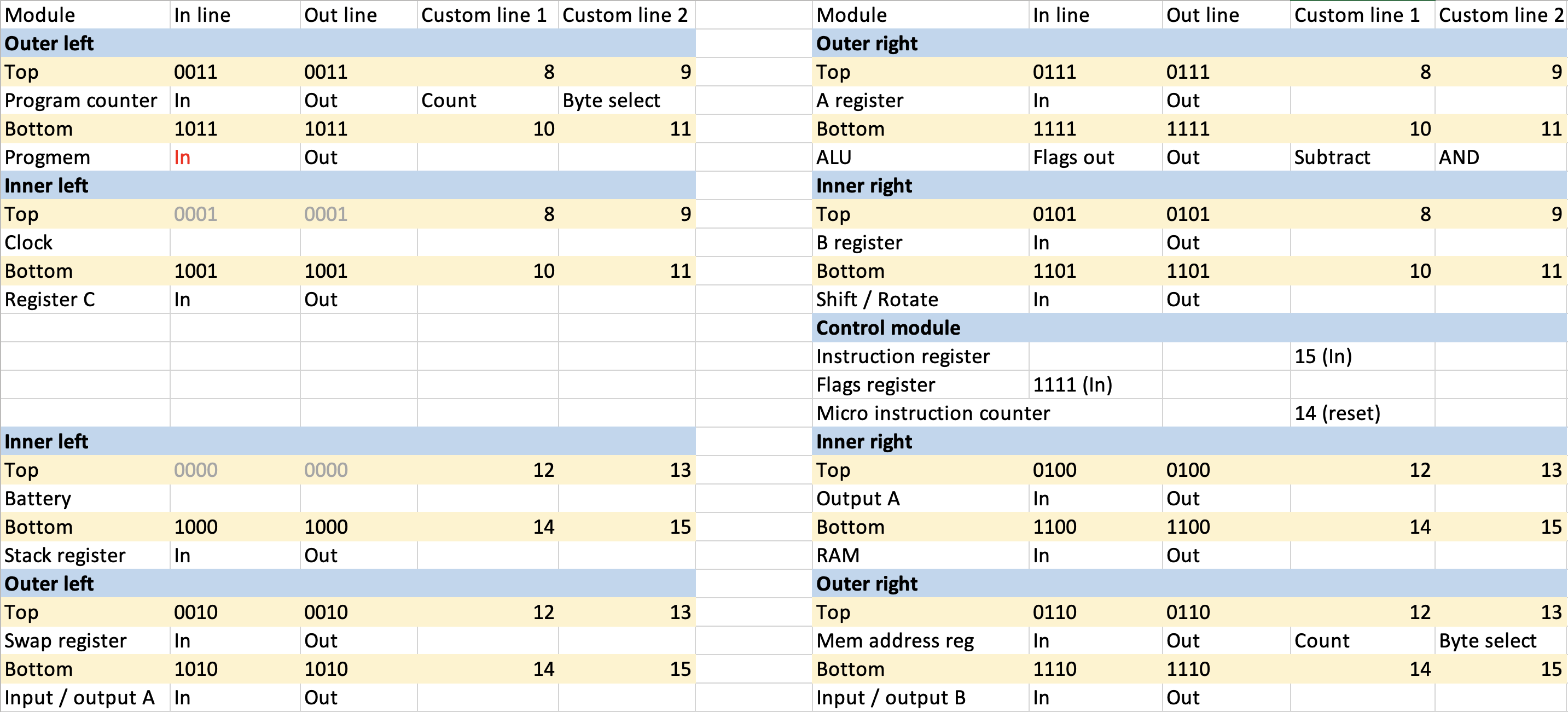
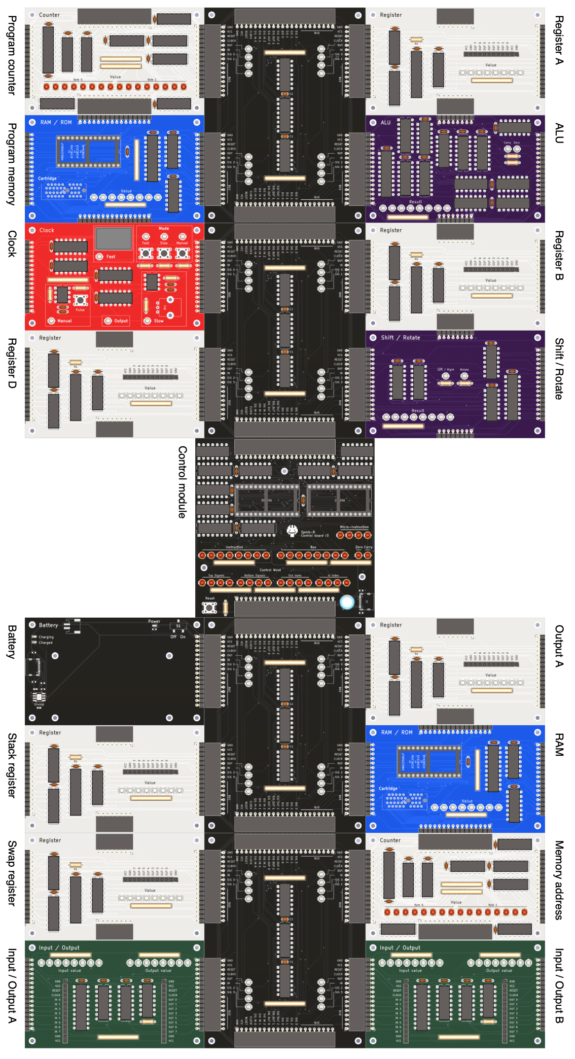
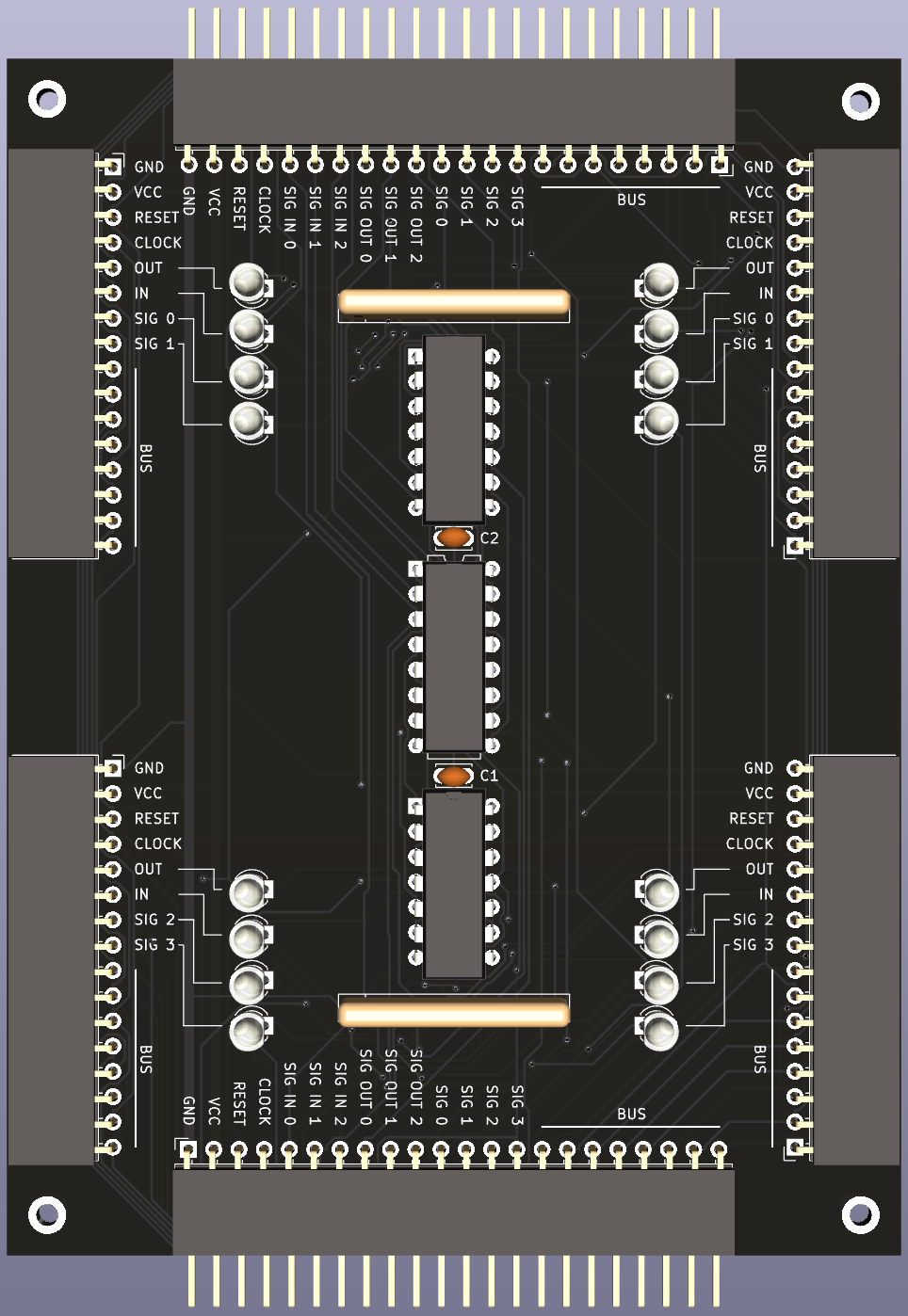
In general, any of the 16 module slots can input from or output to the bus, so most modules could go in any position. However, some of them have to go in specific slots, because:
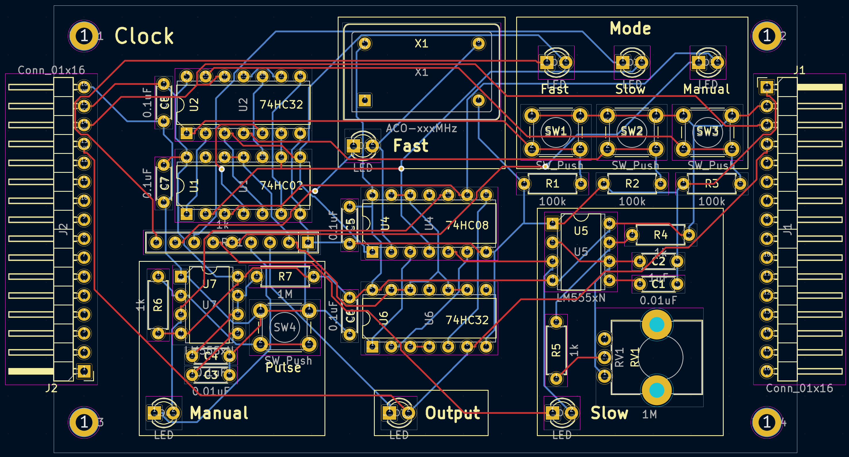
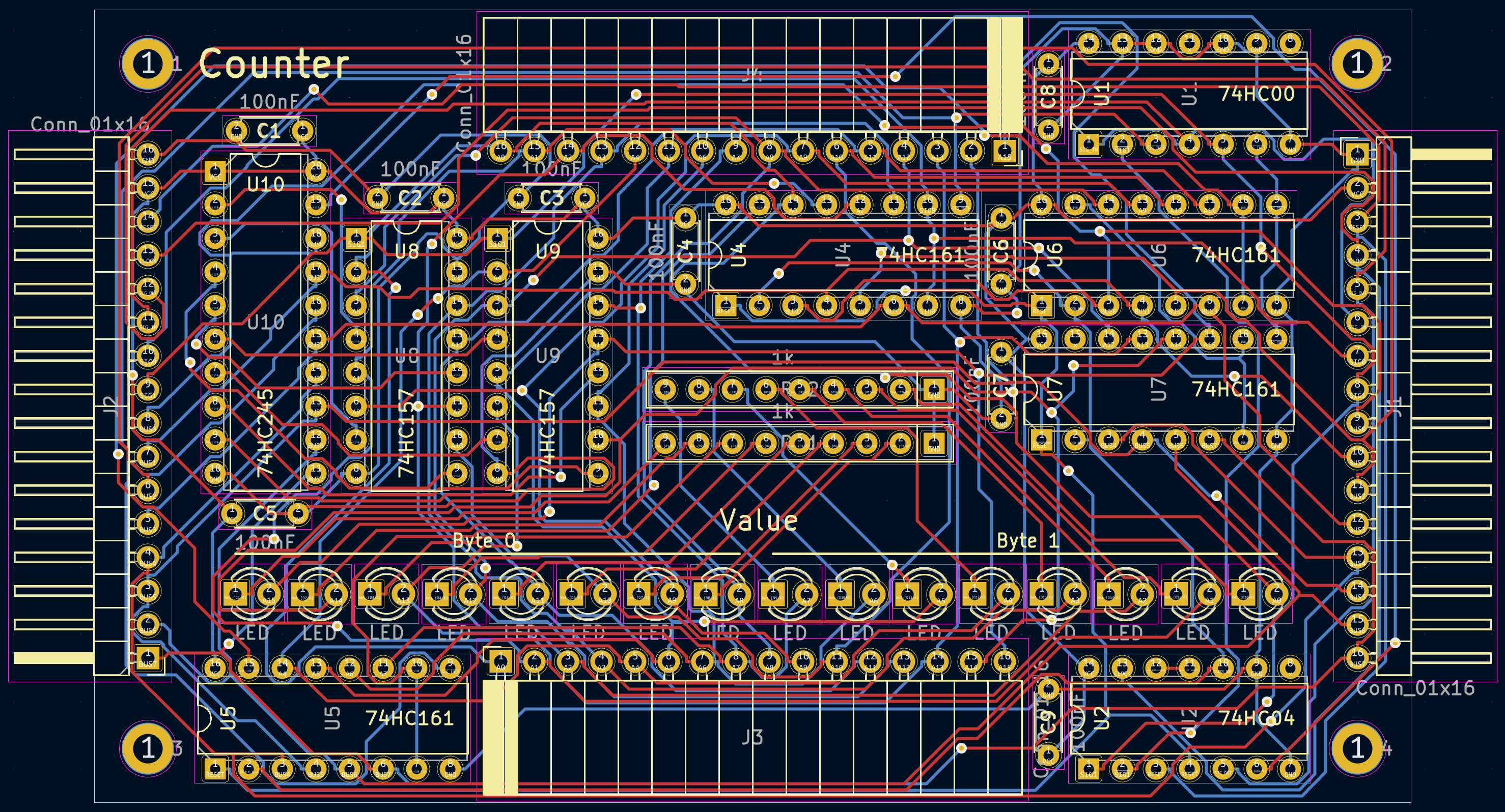
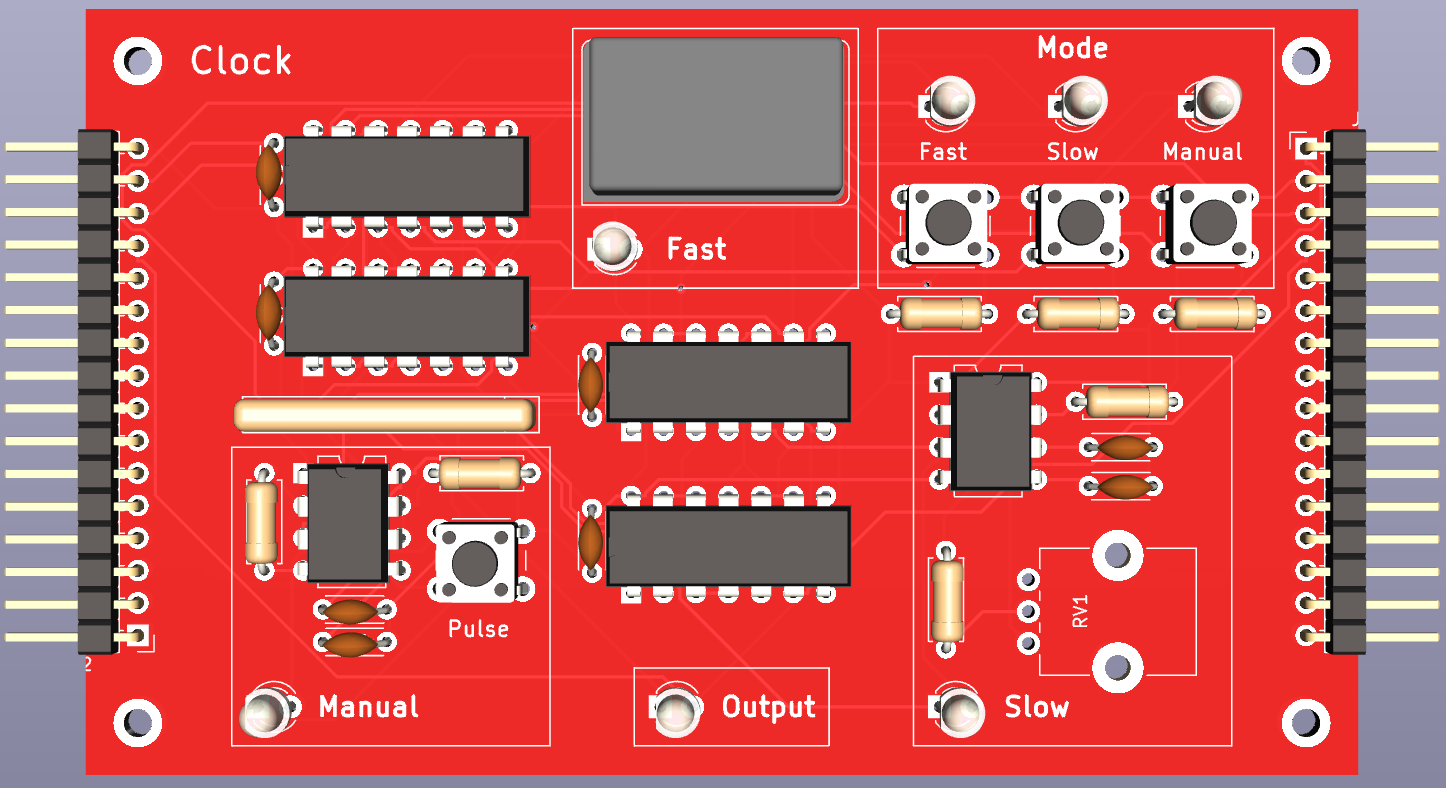
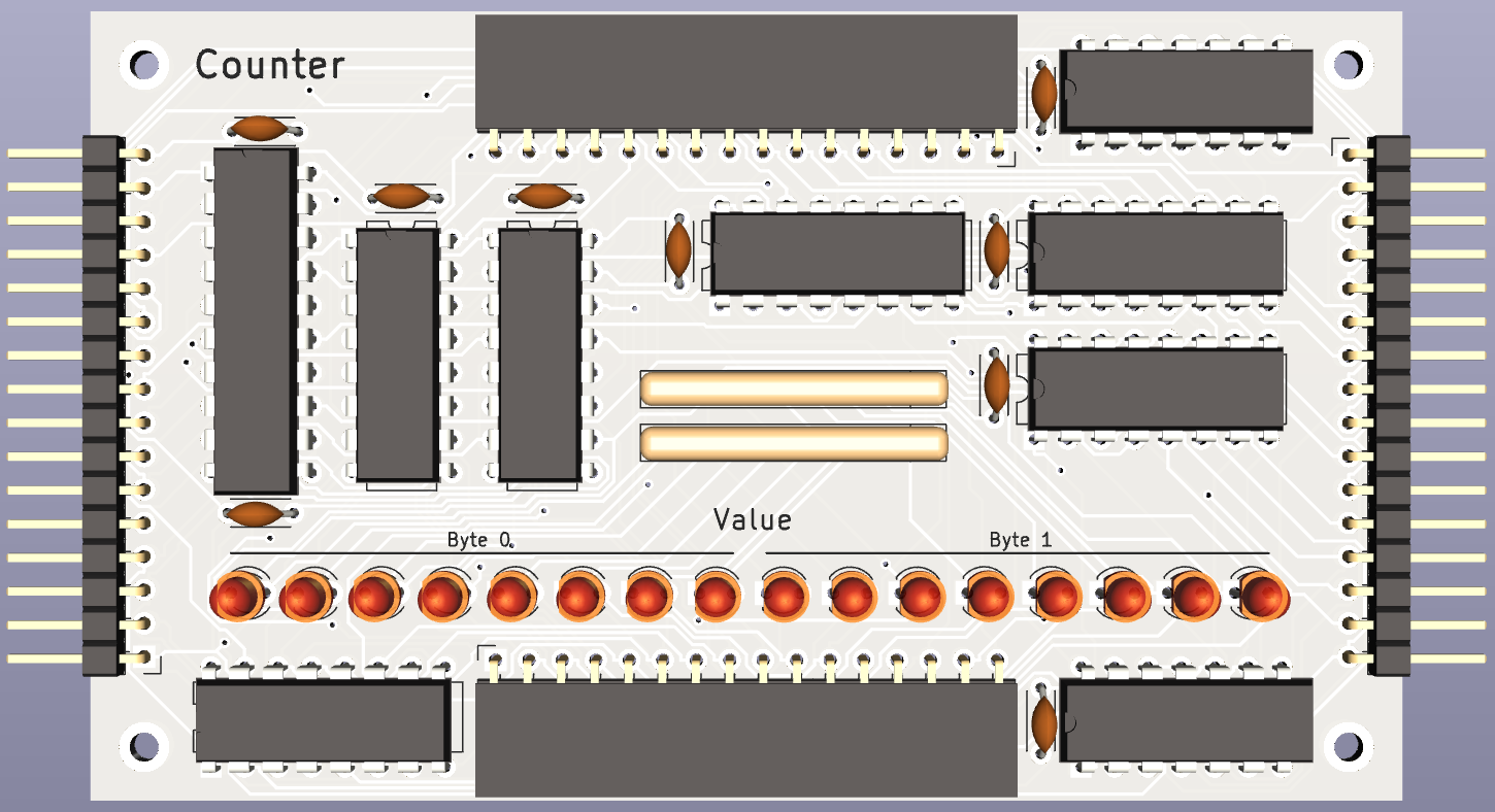
Top left: The program counter goes in the top to use the first pair of custom signals (for count and byte select), plugging into the program memory below it. Below that is the clock (in the 0th position), and Register C.
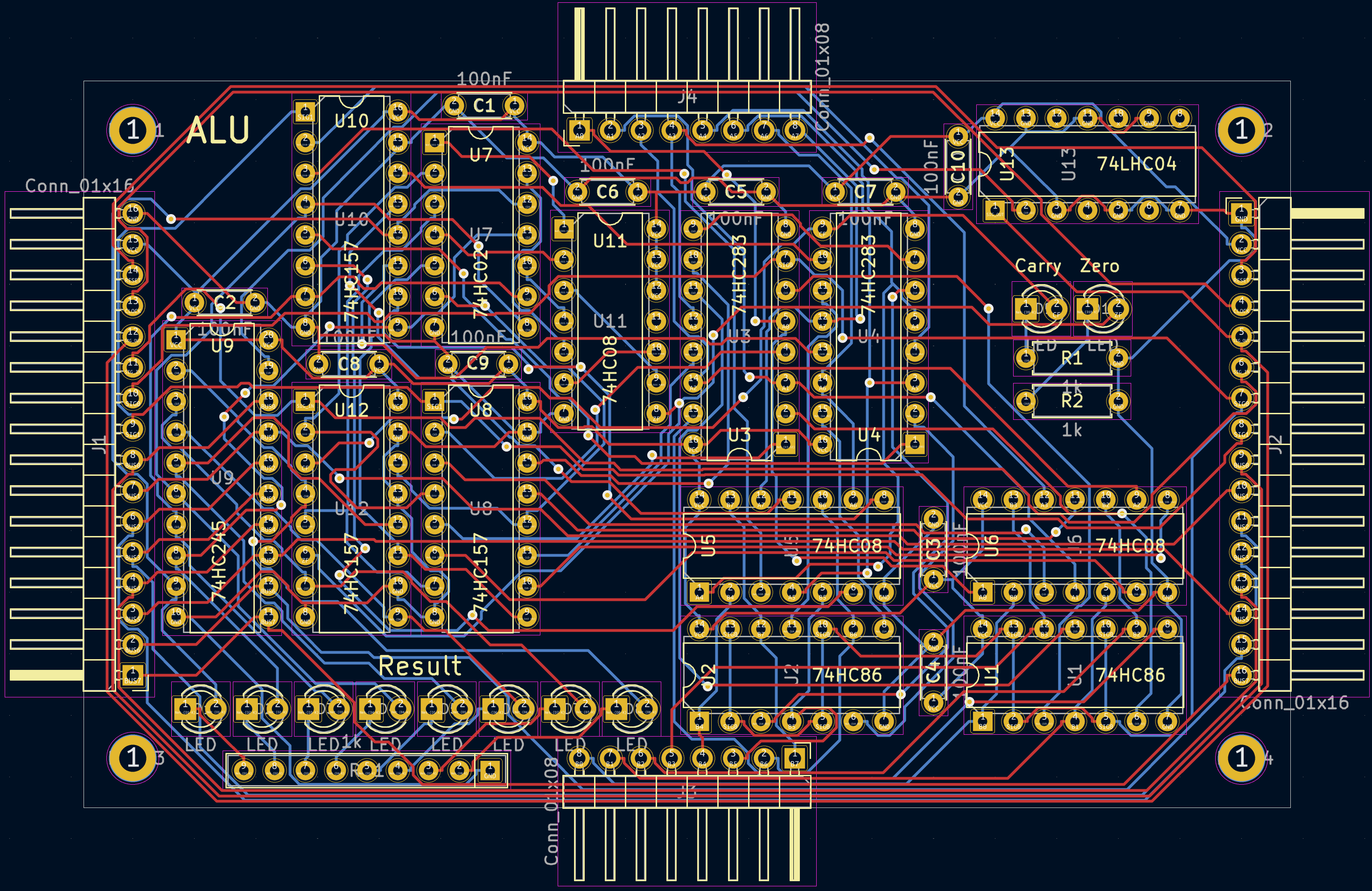
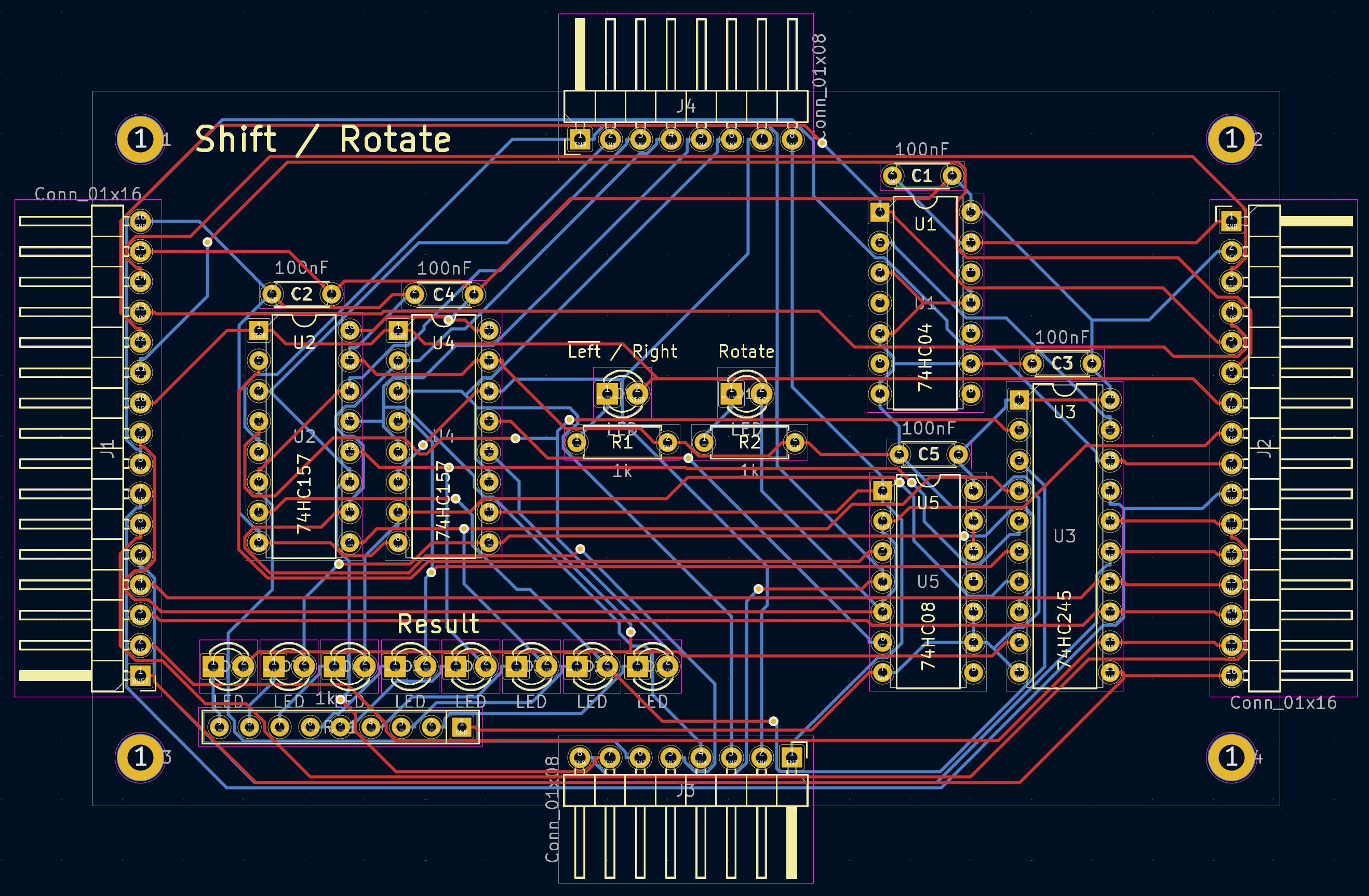
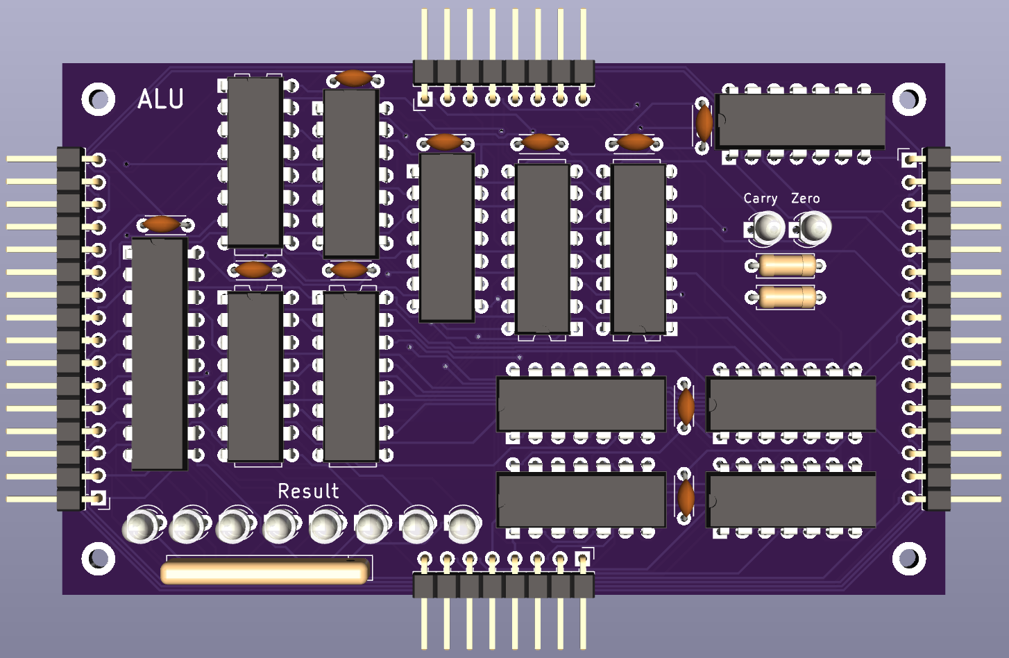
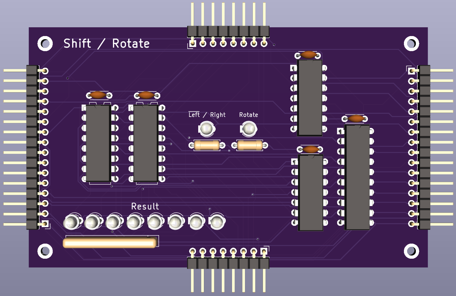
Top right: The ALU goes one slot down from the top, to use the second pair of custom signals (for add/subtract and bit-wise AND), with register A and B as its operands above and below. Then the shift / rotate module goes at the bottom plugging into register B. These need to be on the right side to avoid the 0th position. The shift module shares custom signals with the ALU, which is okay because only one is used at a time, and the signals don't have an effect if that module isn't outputting.
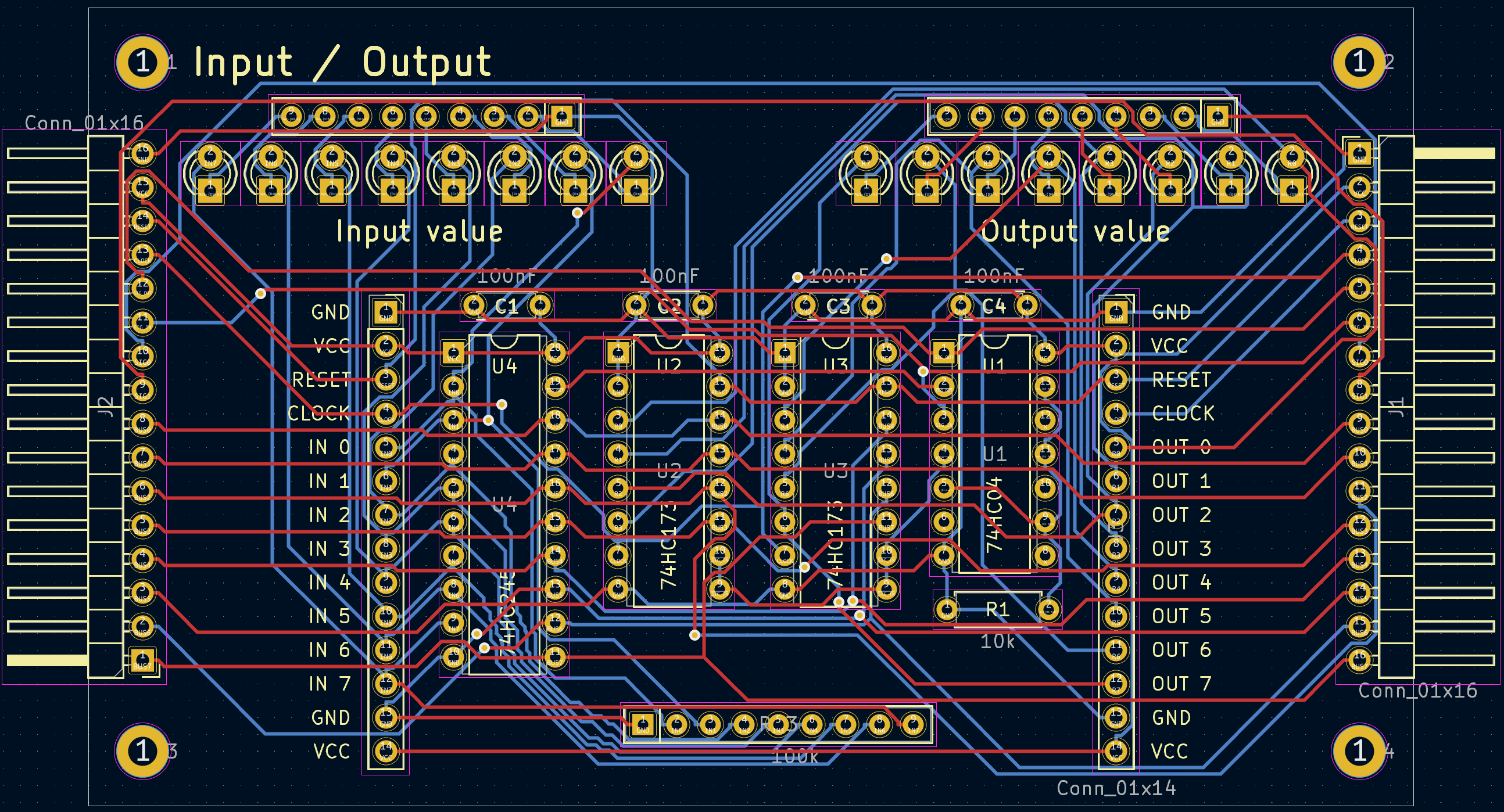
Bottom left: The battery takes the top 0th slot, and then the stack and swap registers, and input / output A module after that. Other than the battery, the positions are arbitrary.
Bottom right: The output A register goes at the top and the RAM goes below it. The memory address register goes in the next position to get the first pair of custom signals (for count and byte select), and plugs into the RAM above it. The input / output B module goes at the bottom. The memory address could instead go where output A is, and RAM just needs to be next to it. The other two could go anywhere.
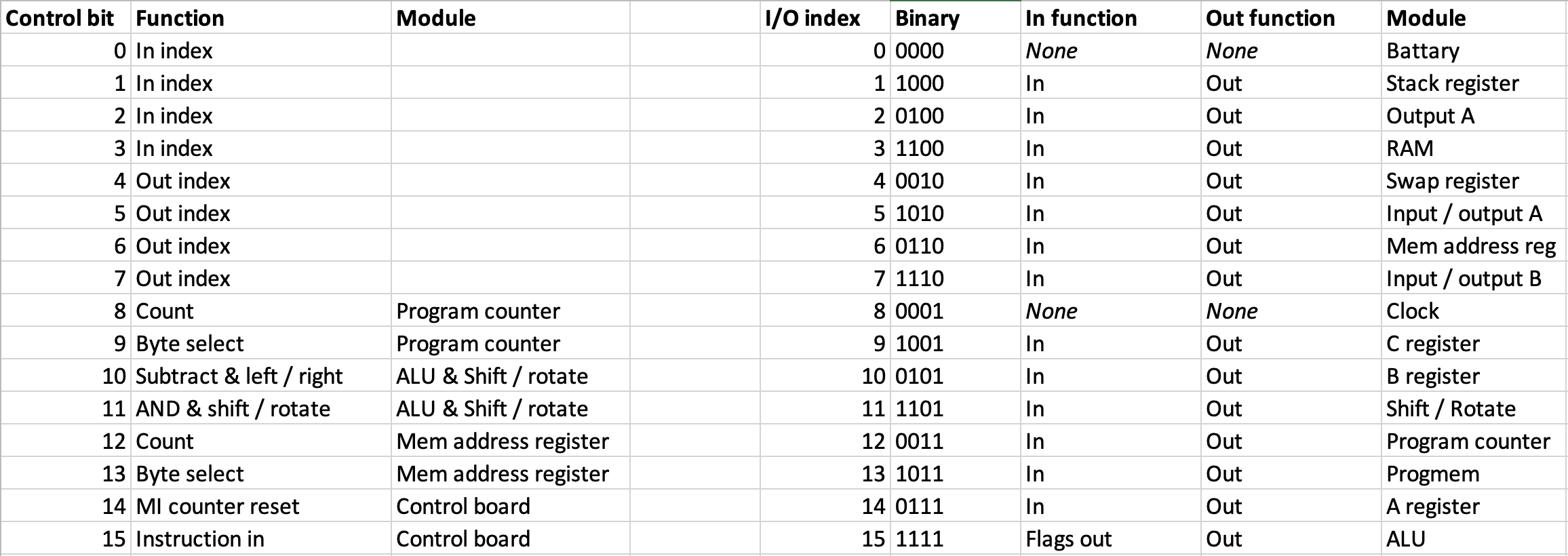
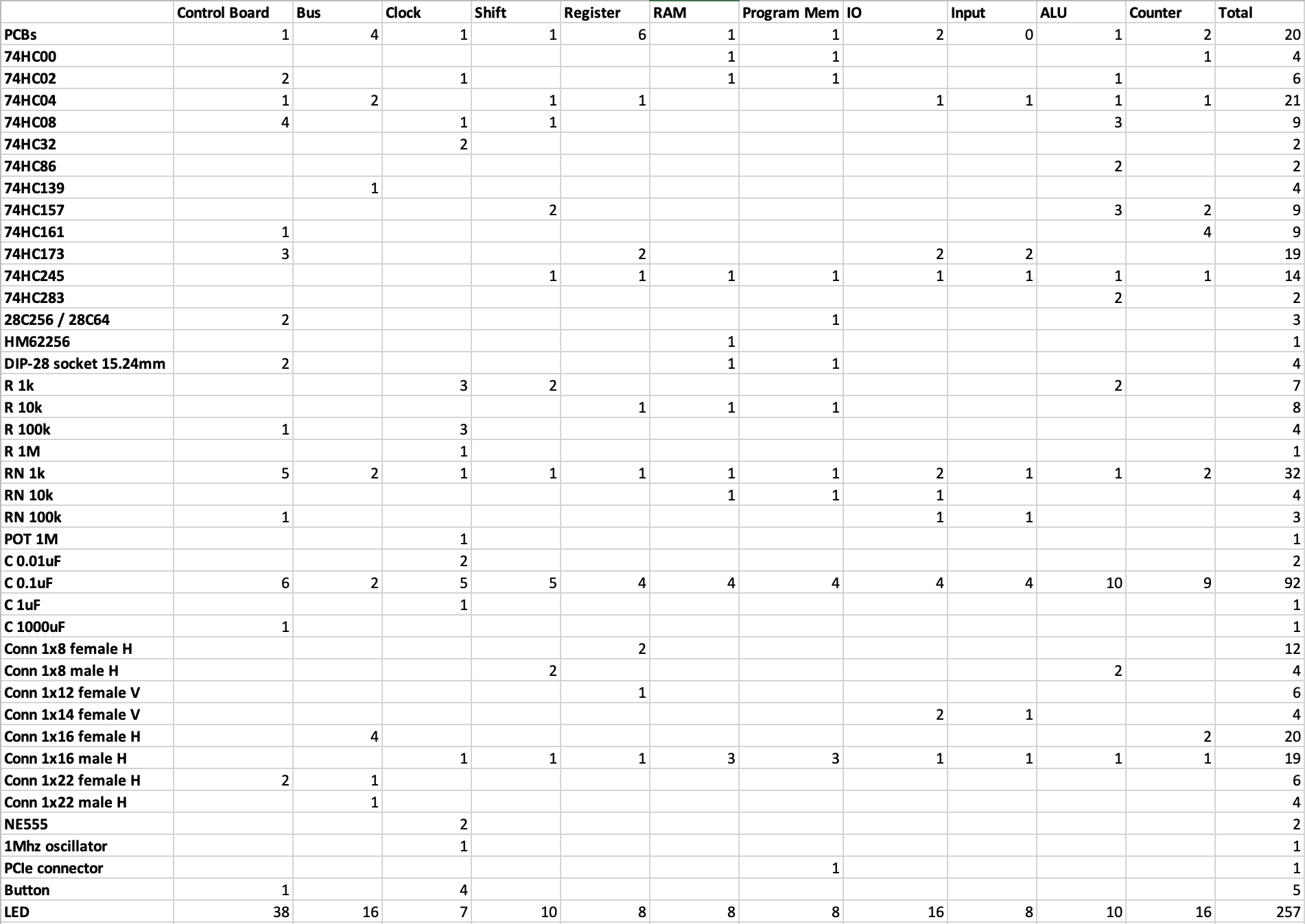
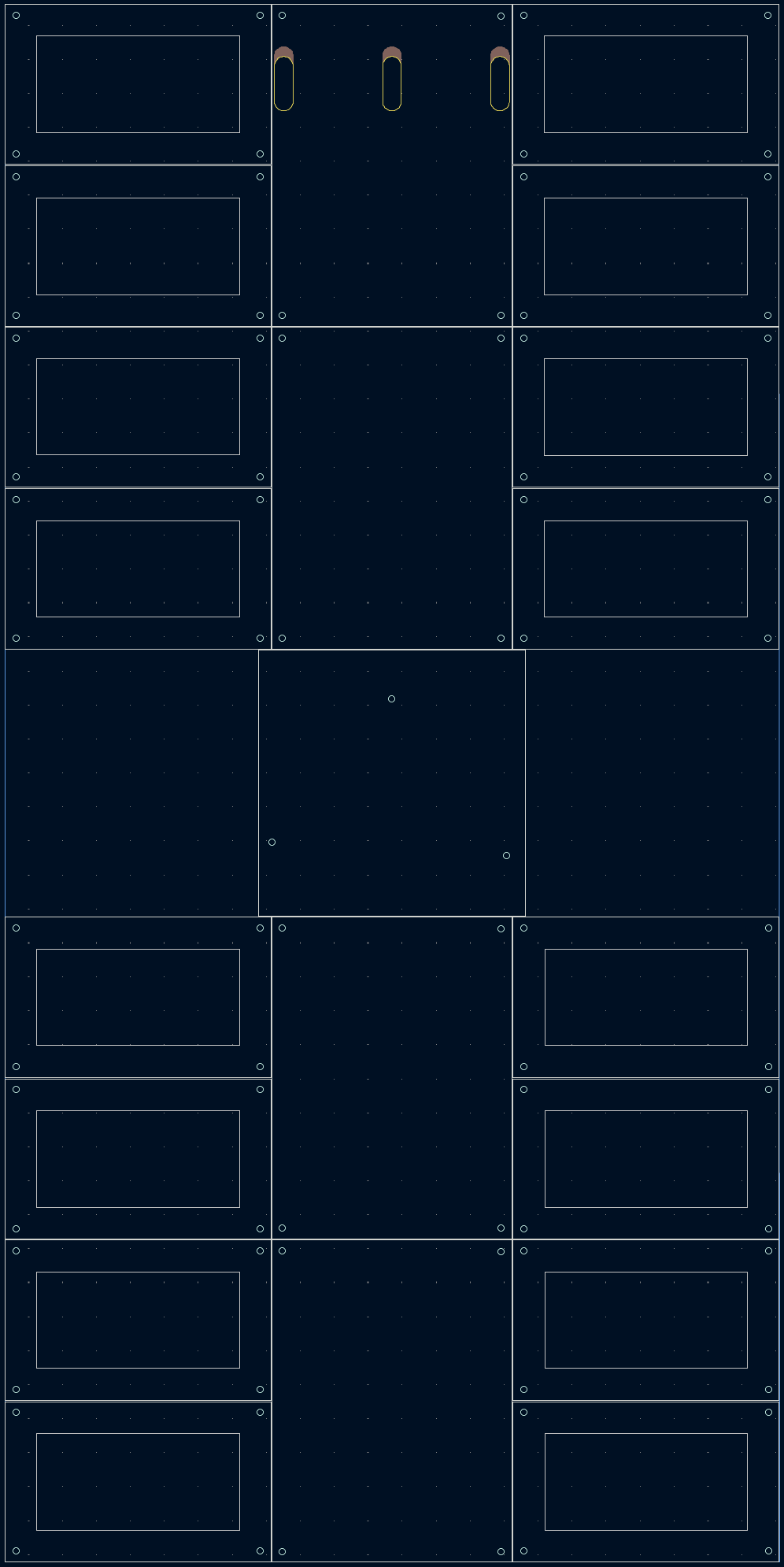
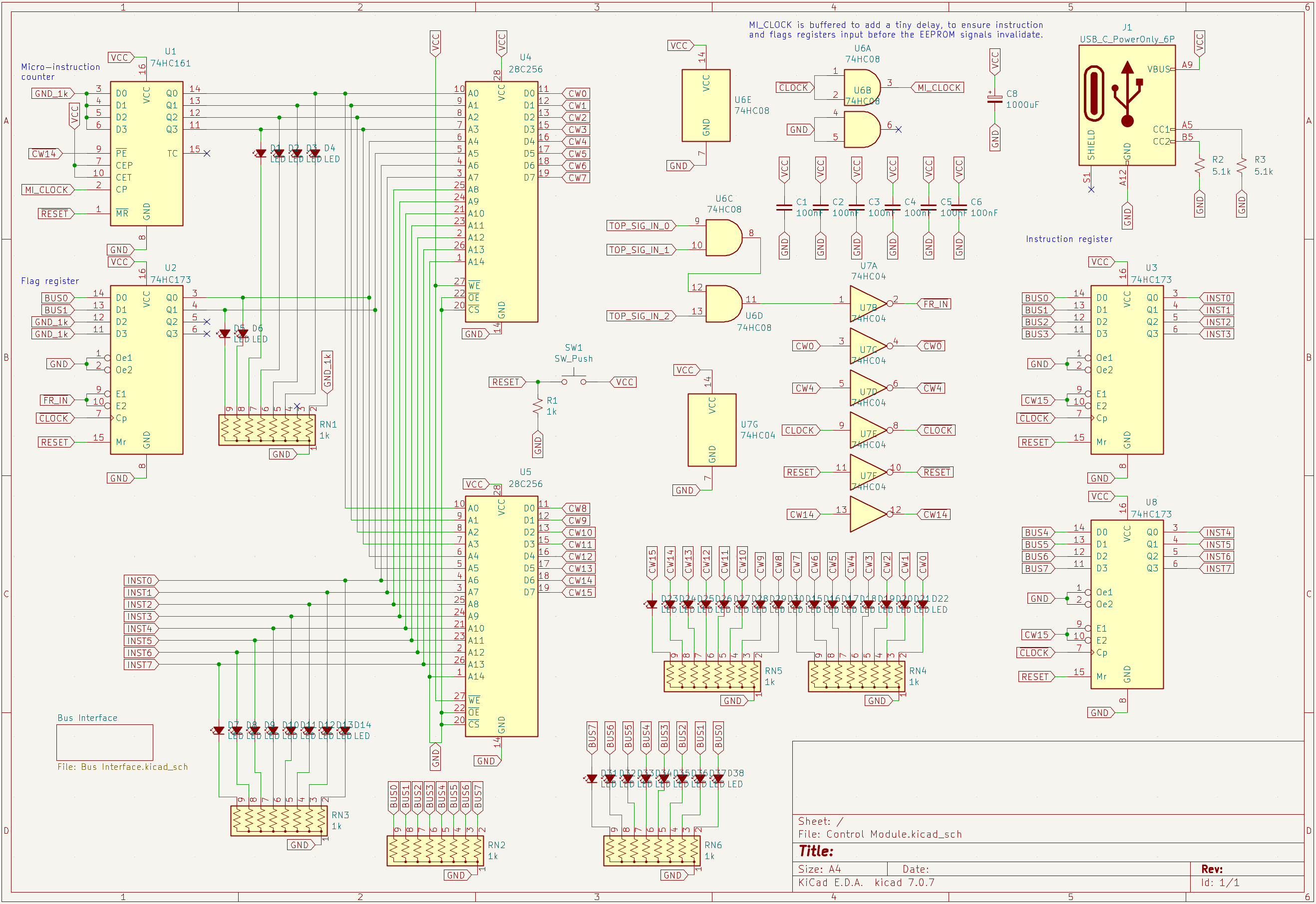
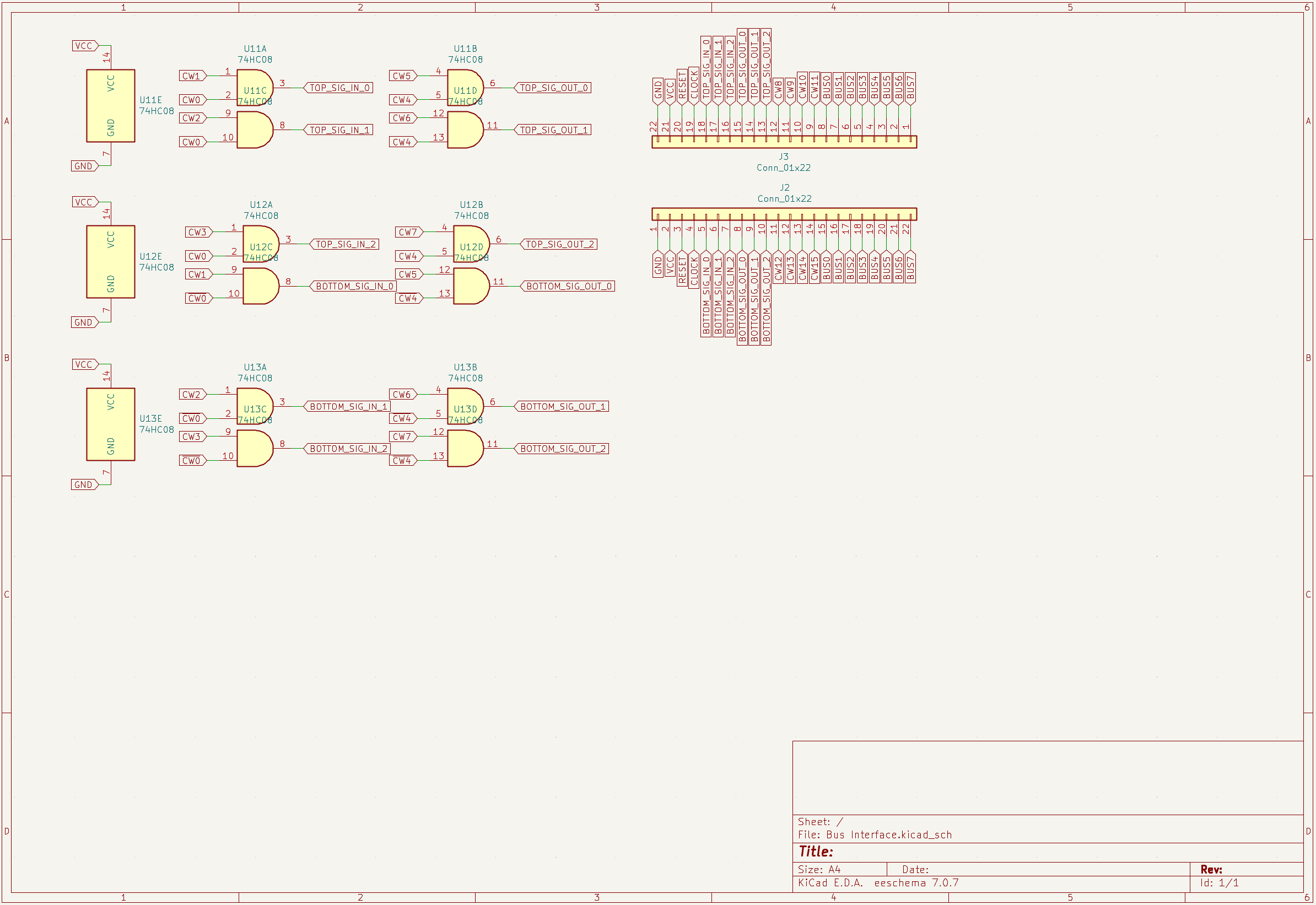
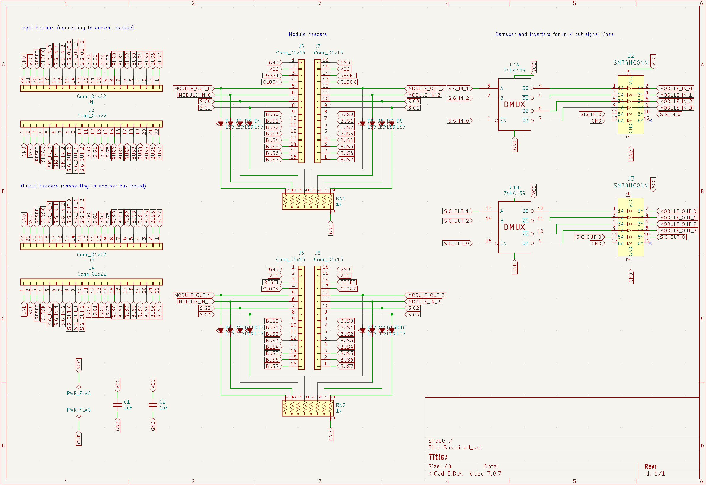
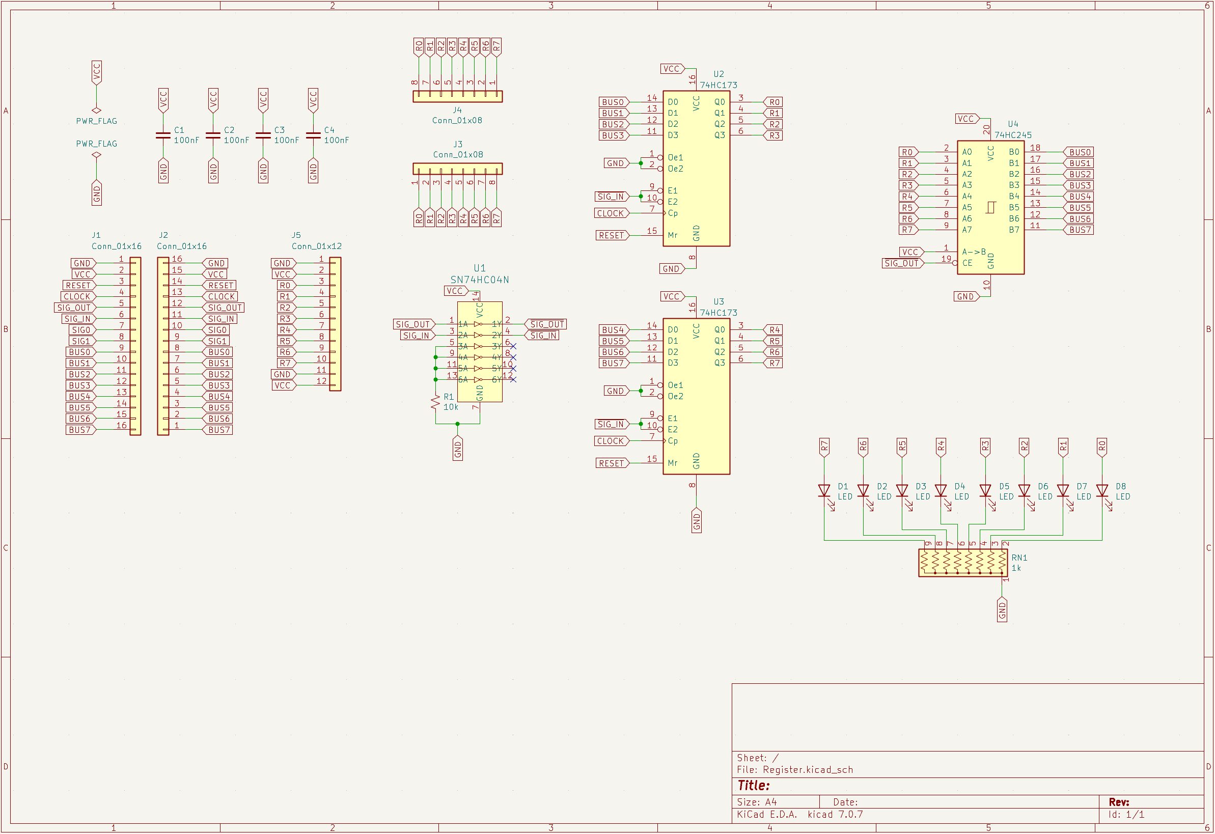
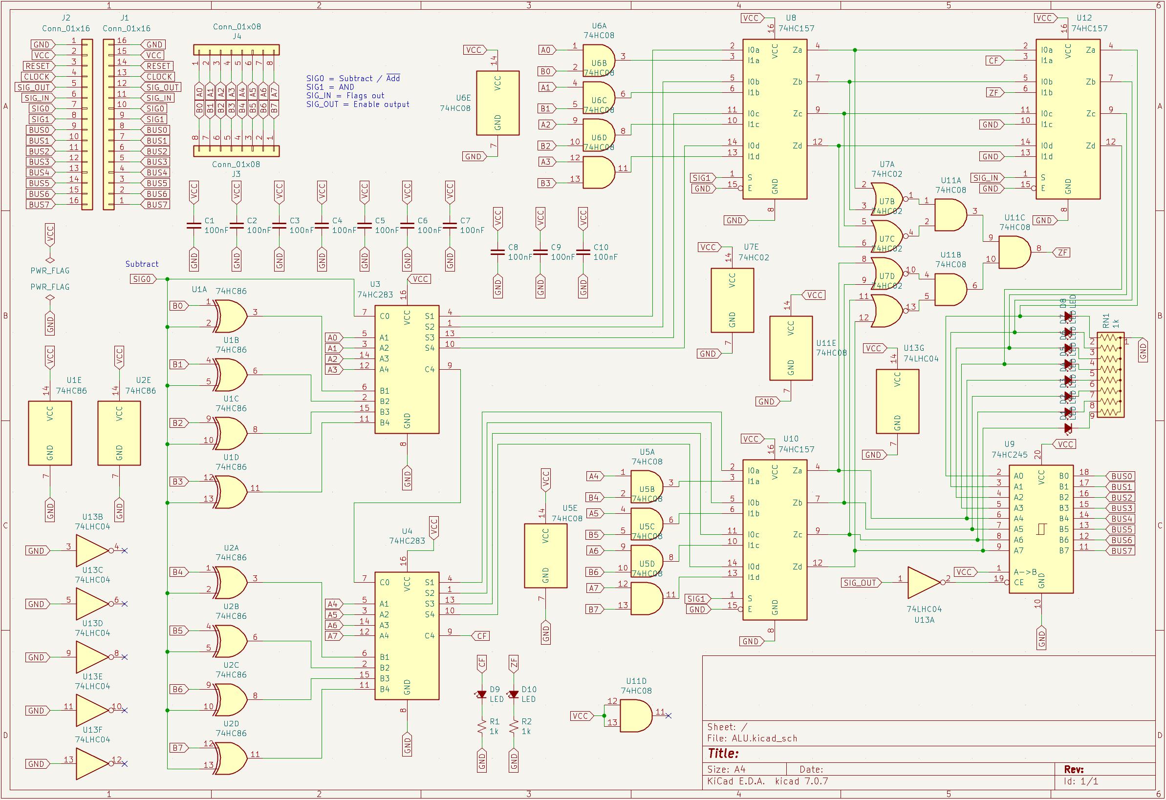
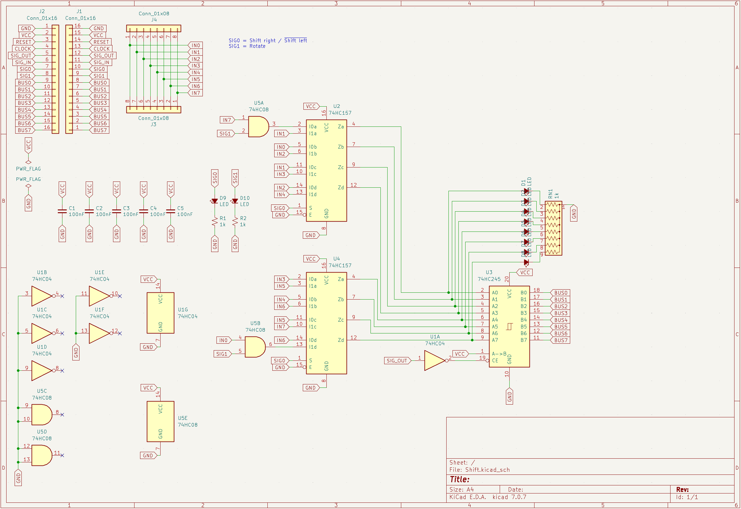
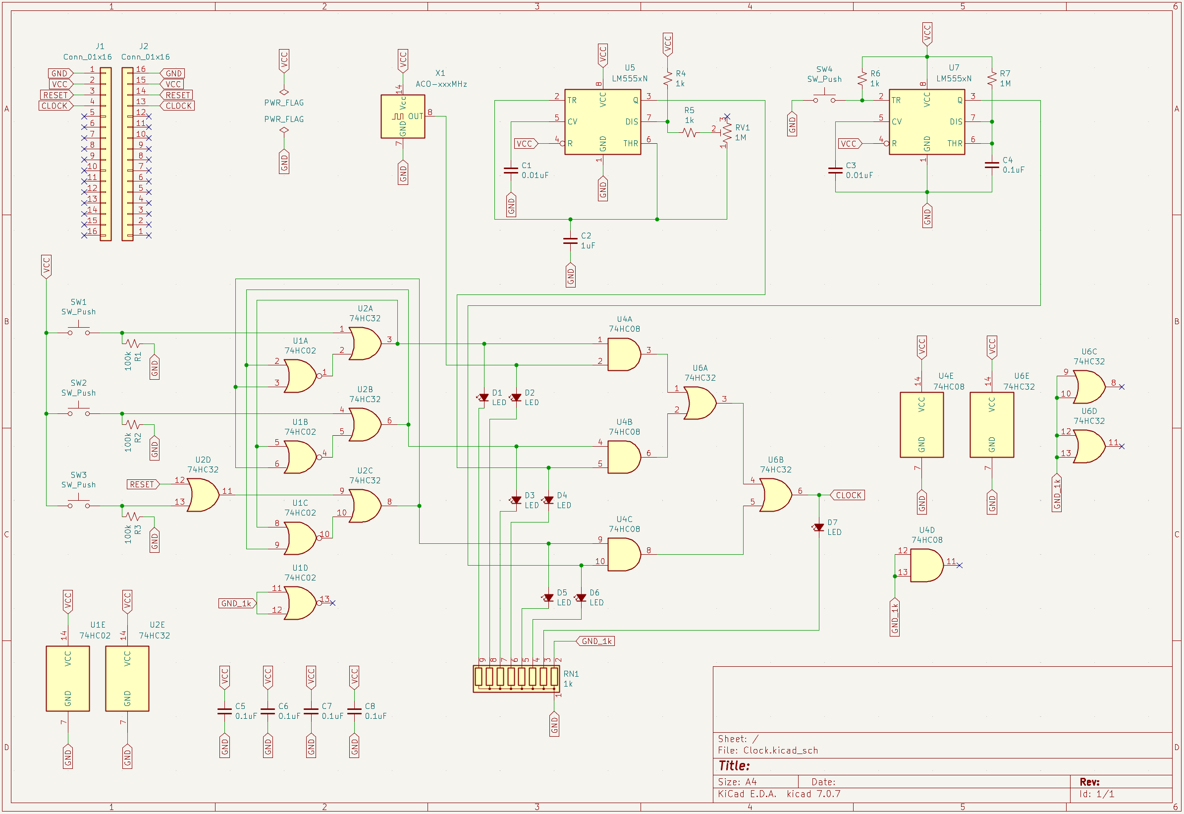
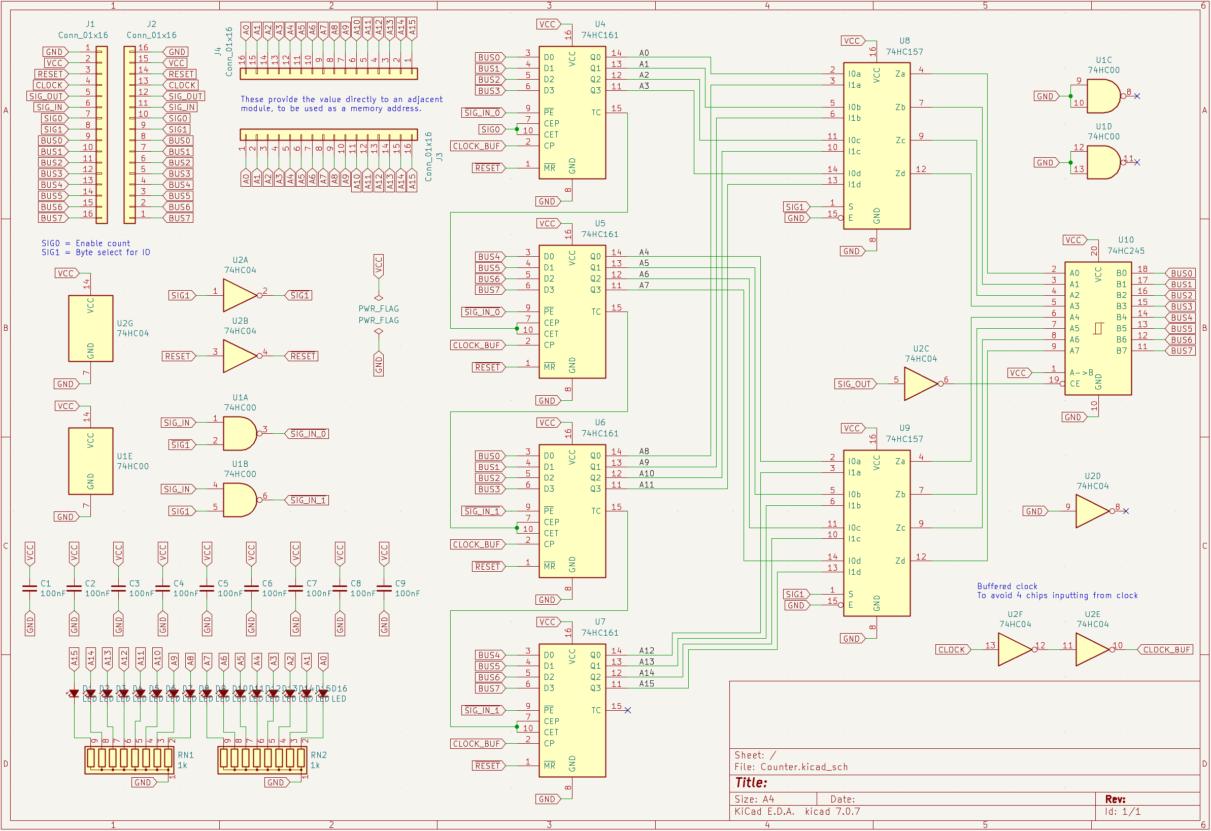
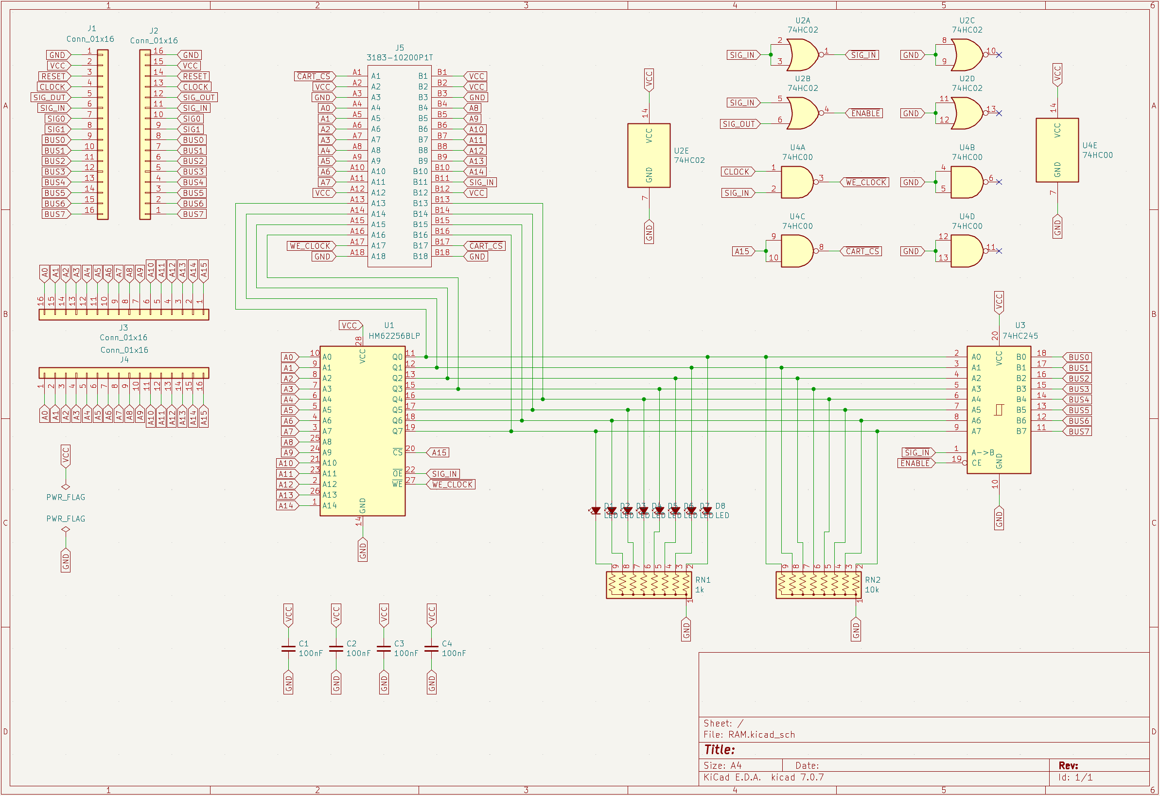
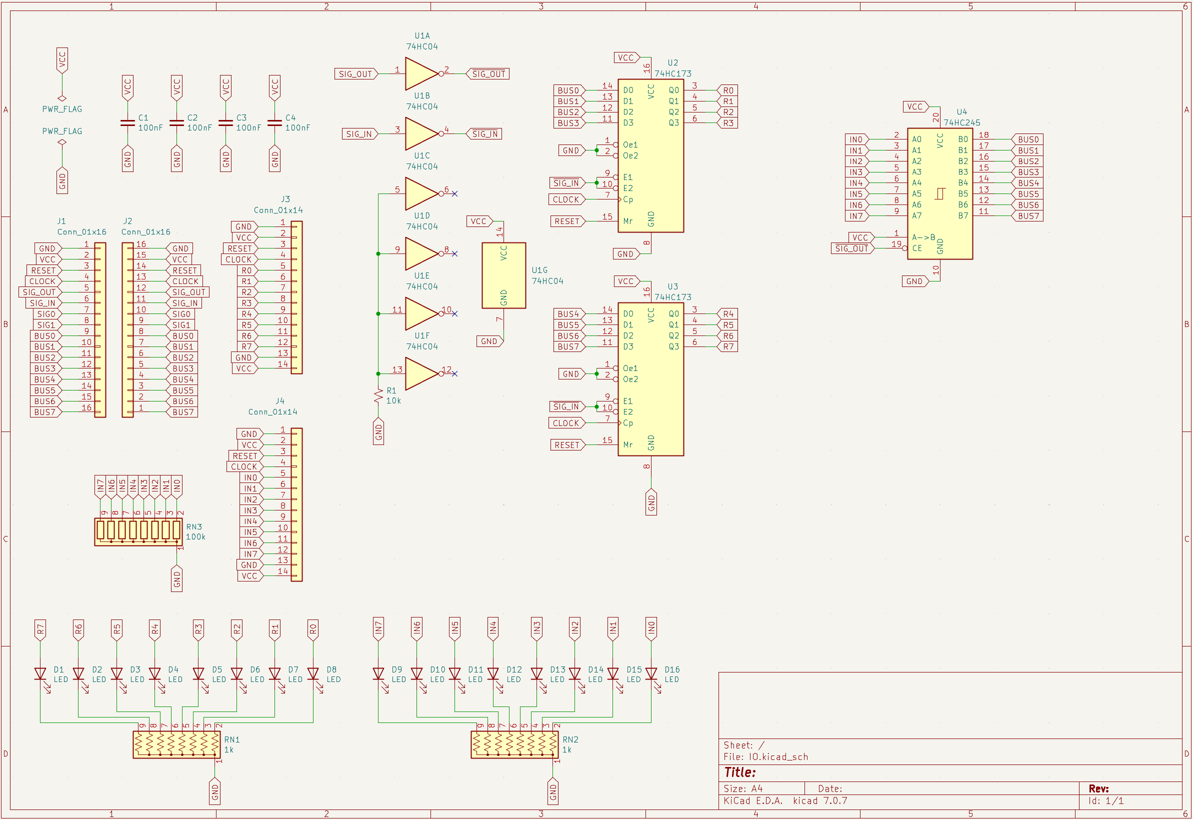
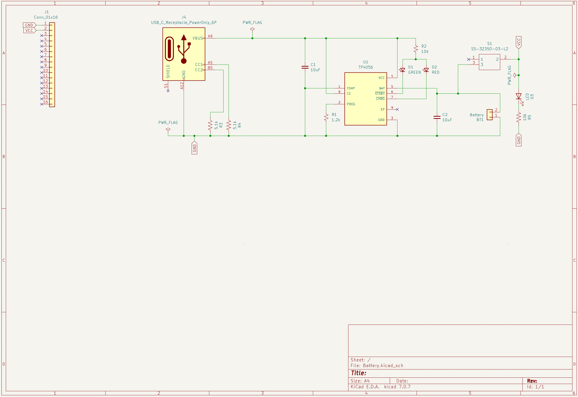
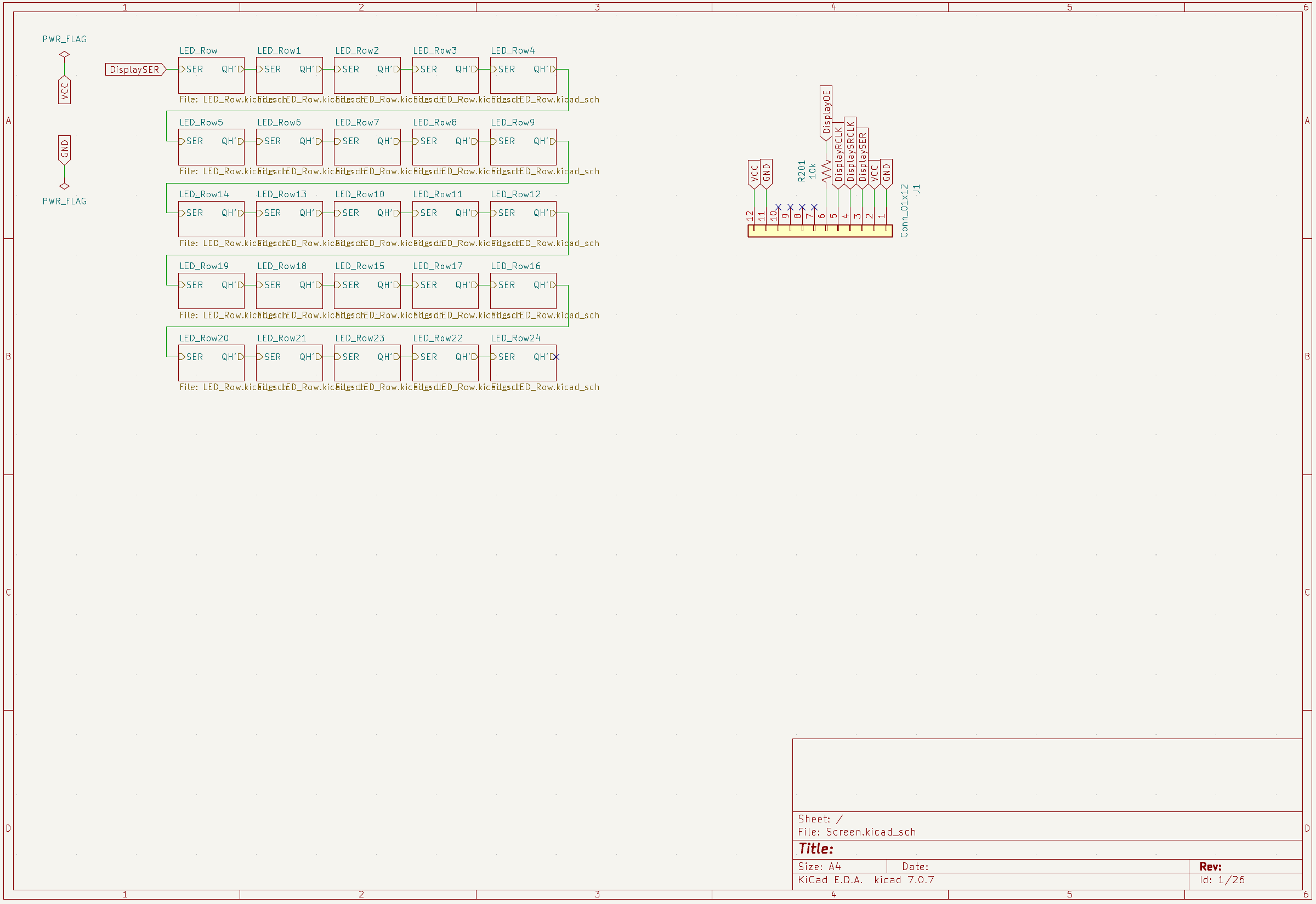
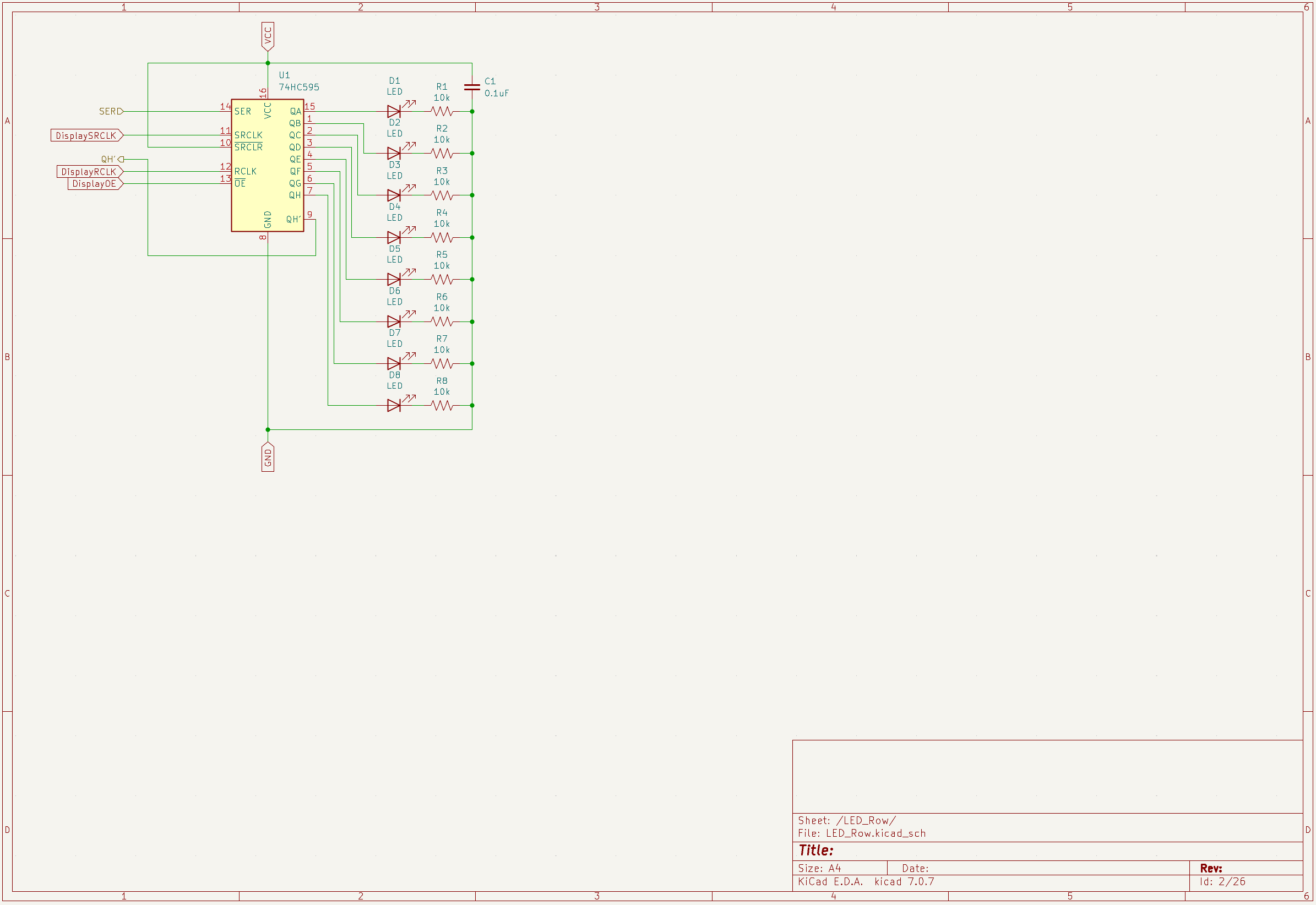
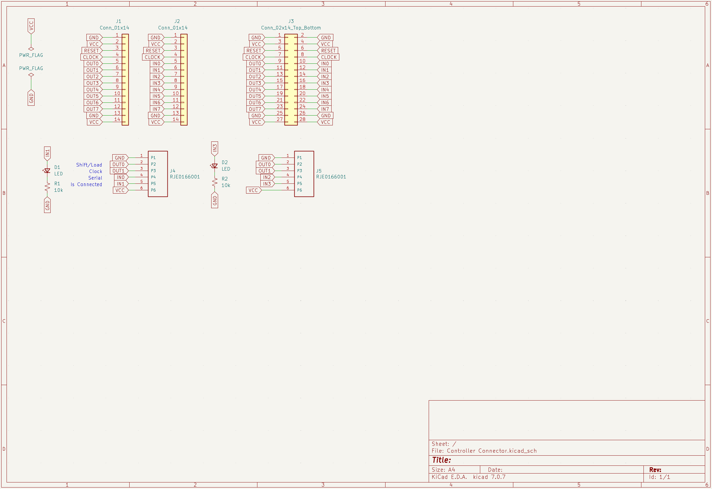
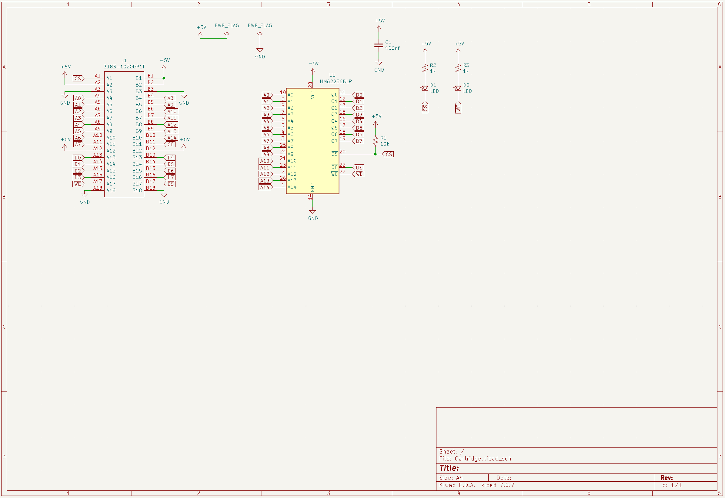
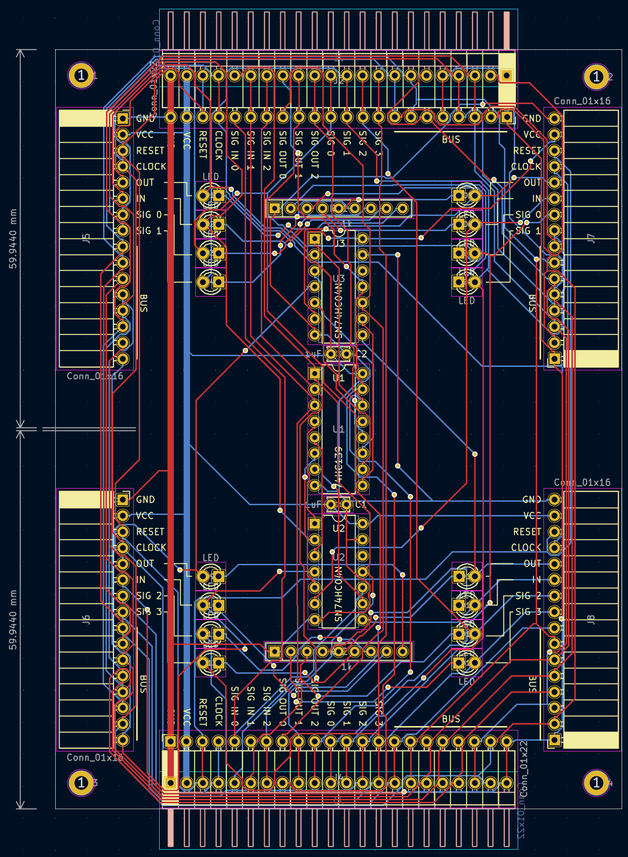
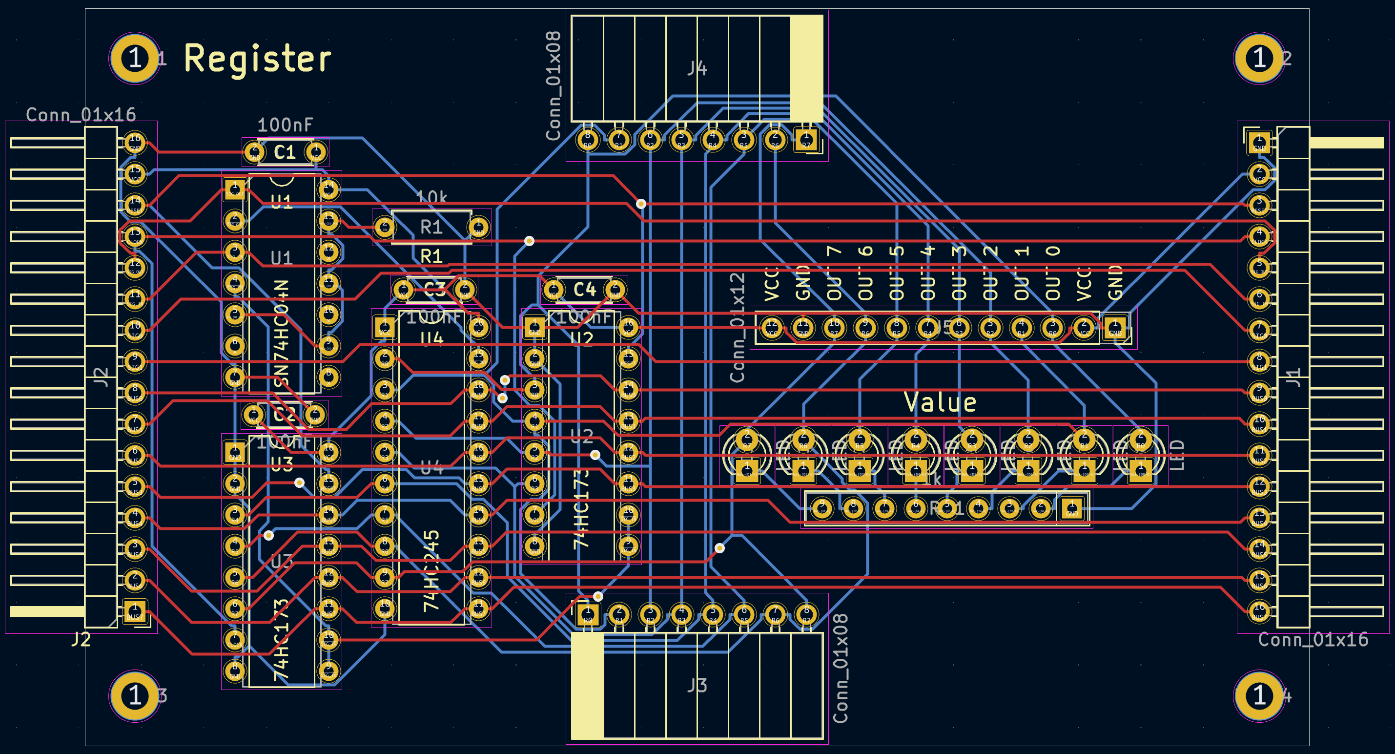
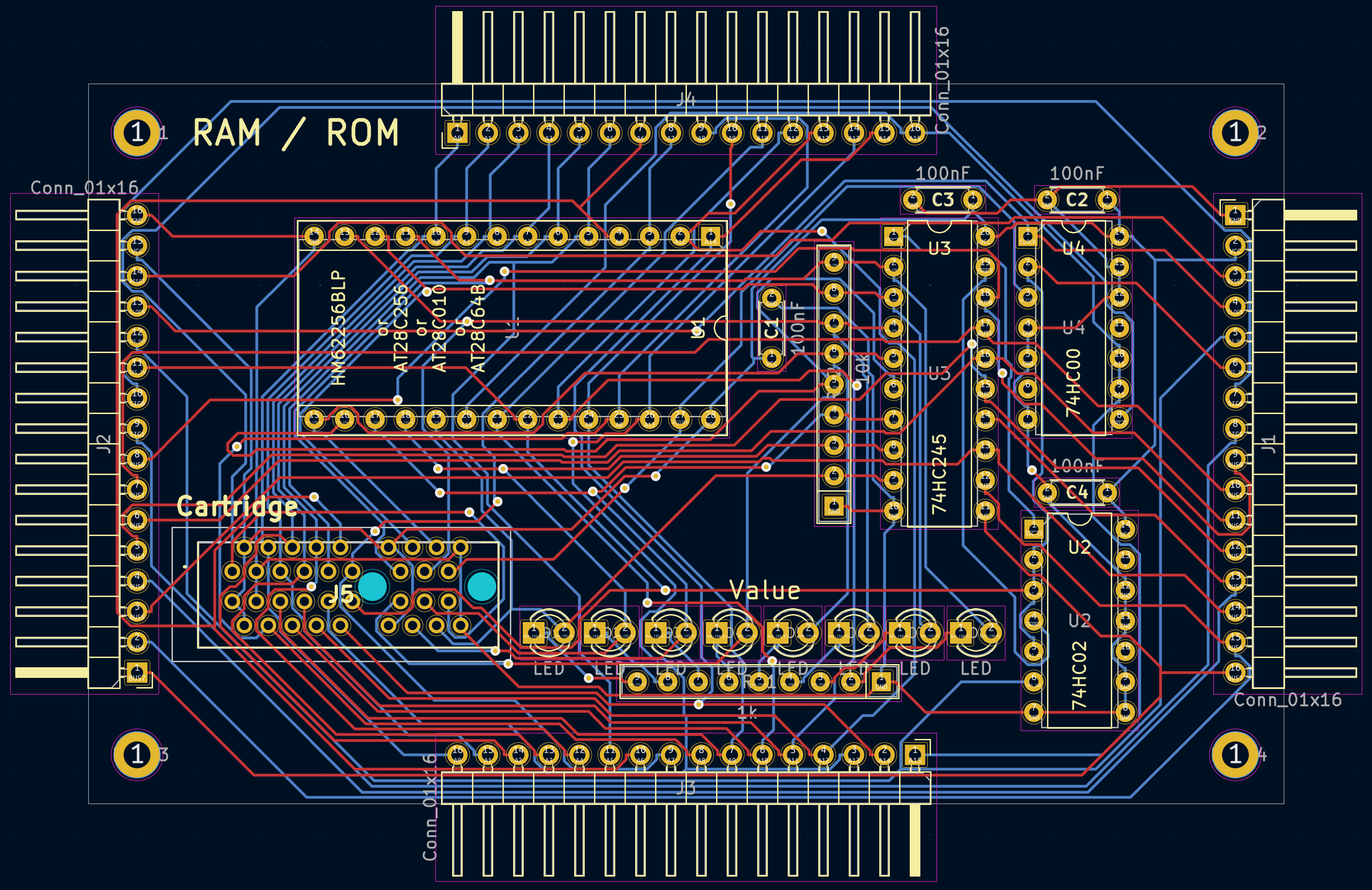
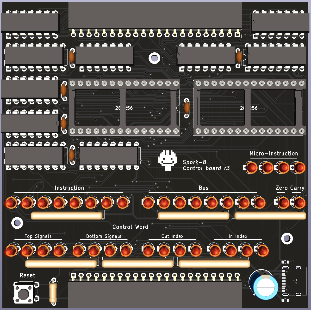
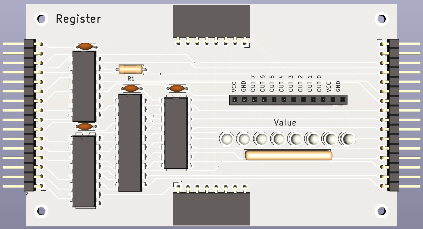
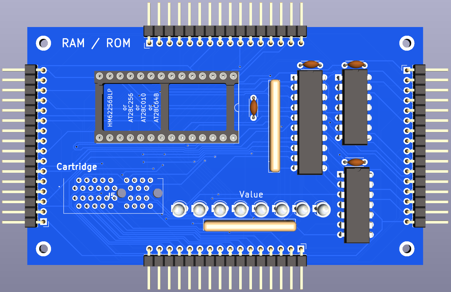
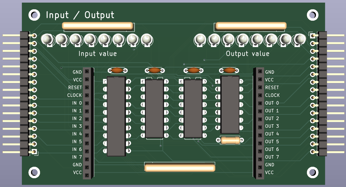
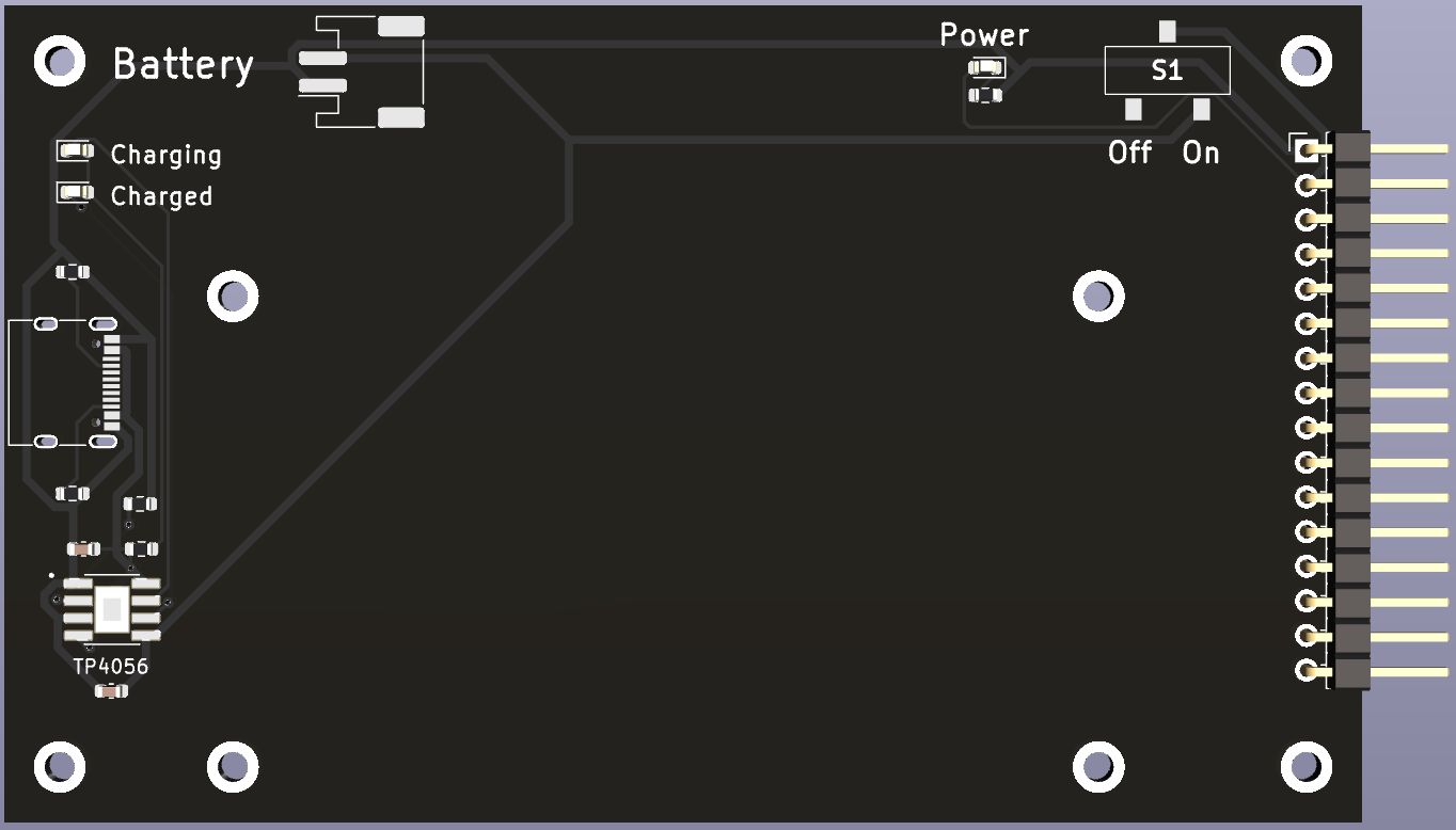
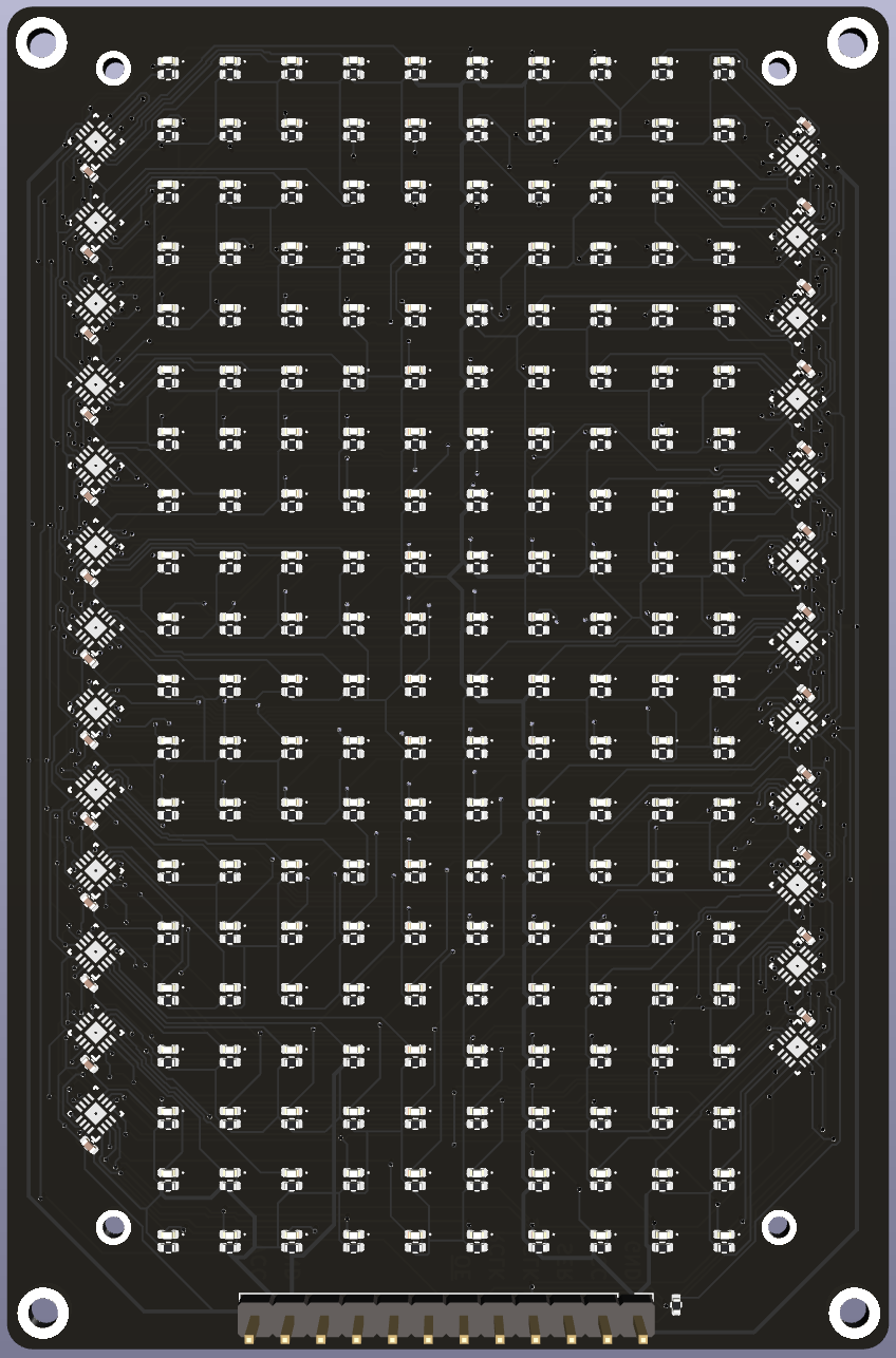
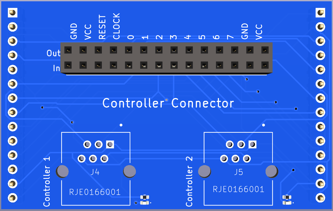
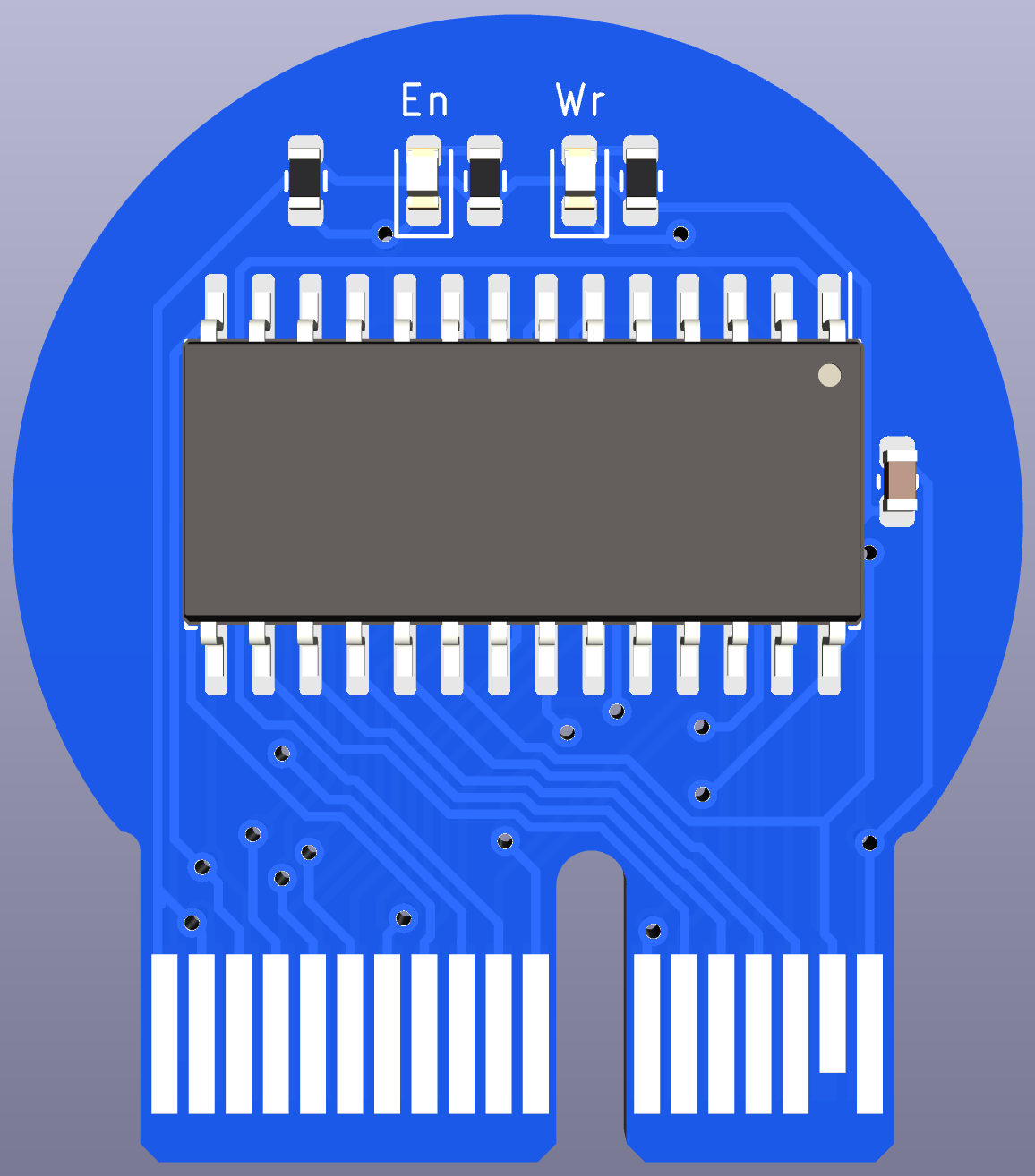
These images show the layout of the modules in the 16 slots, the functions of each of the signals, and a parts list.
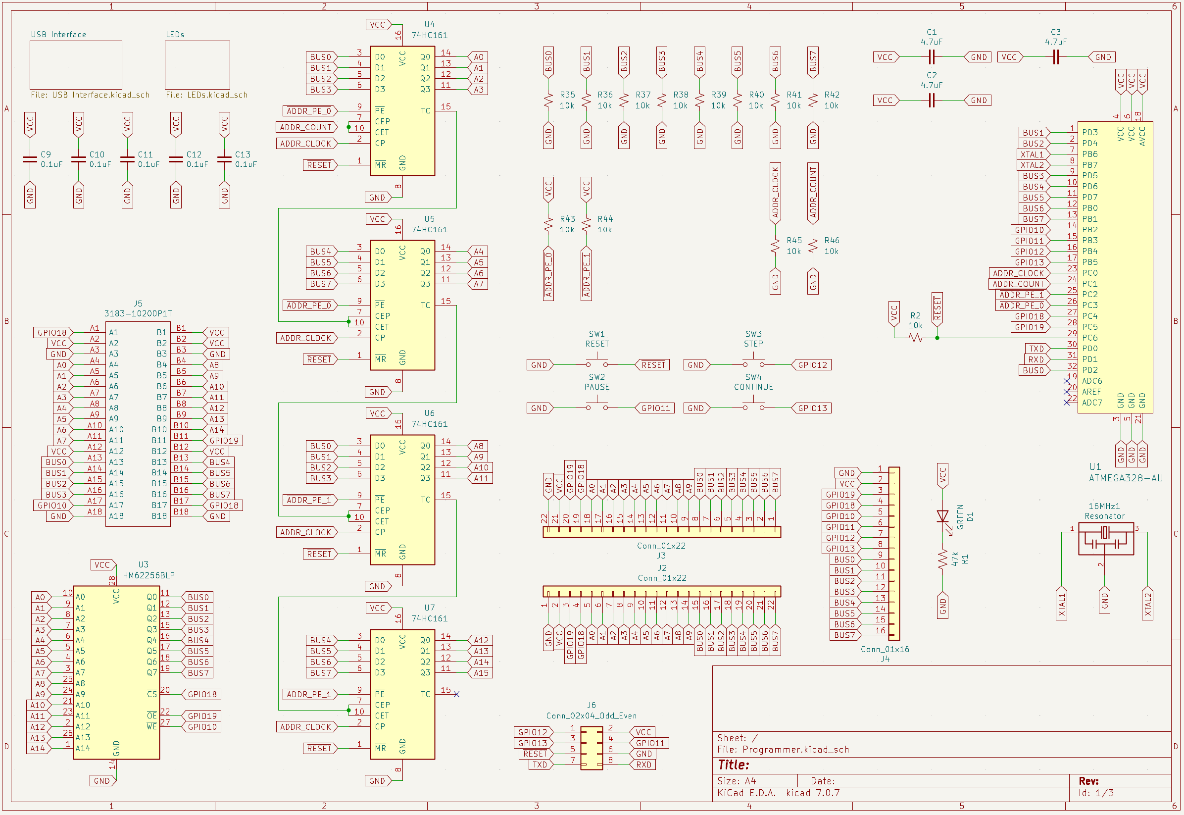
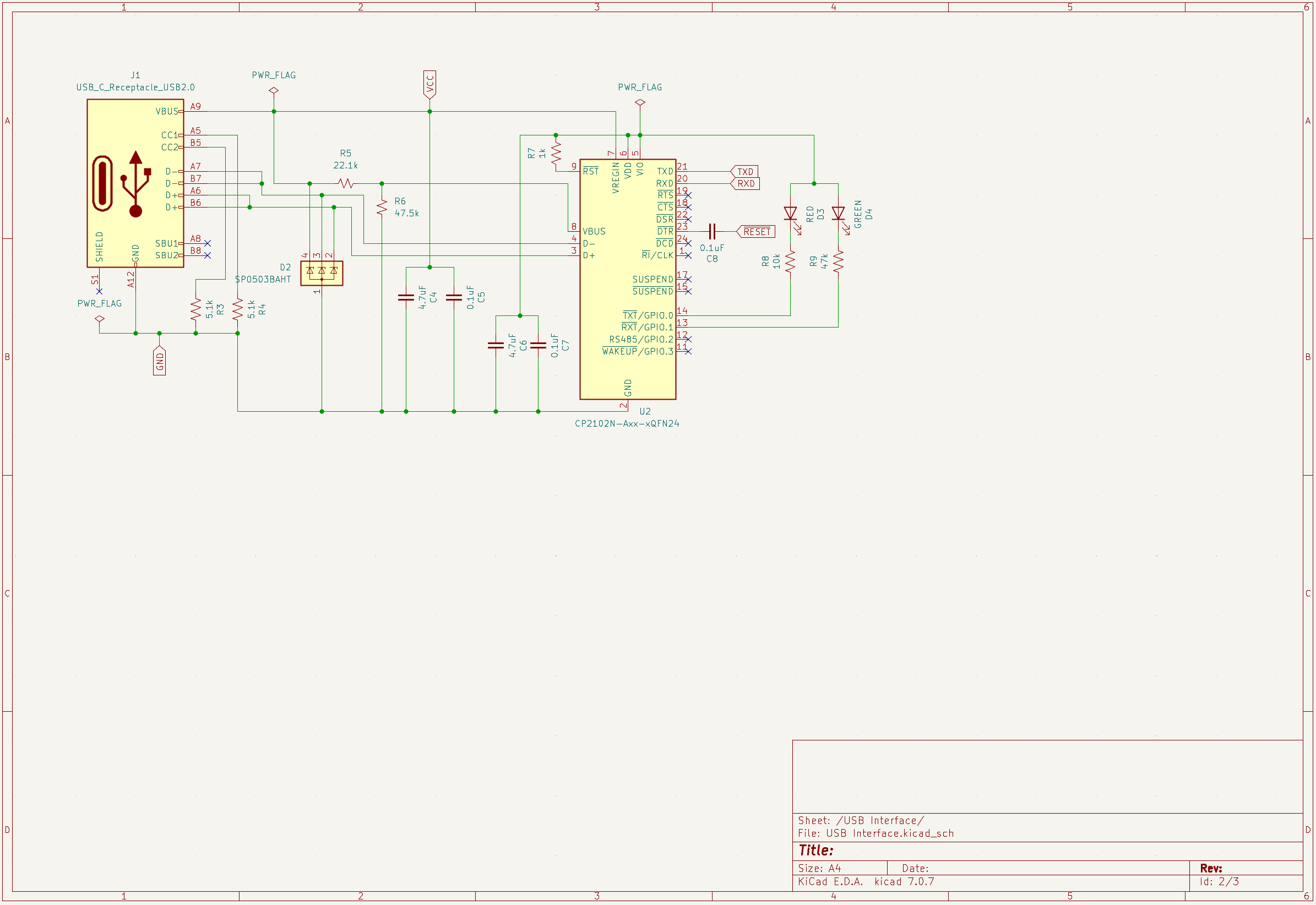
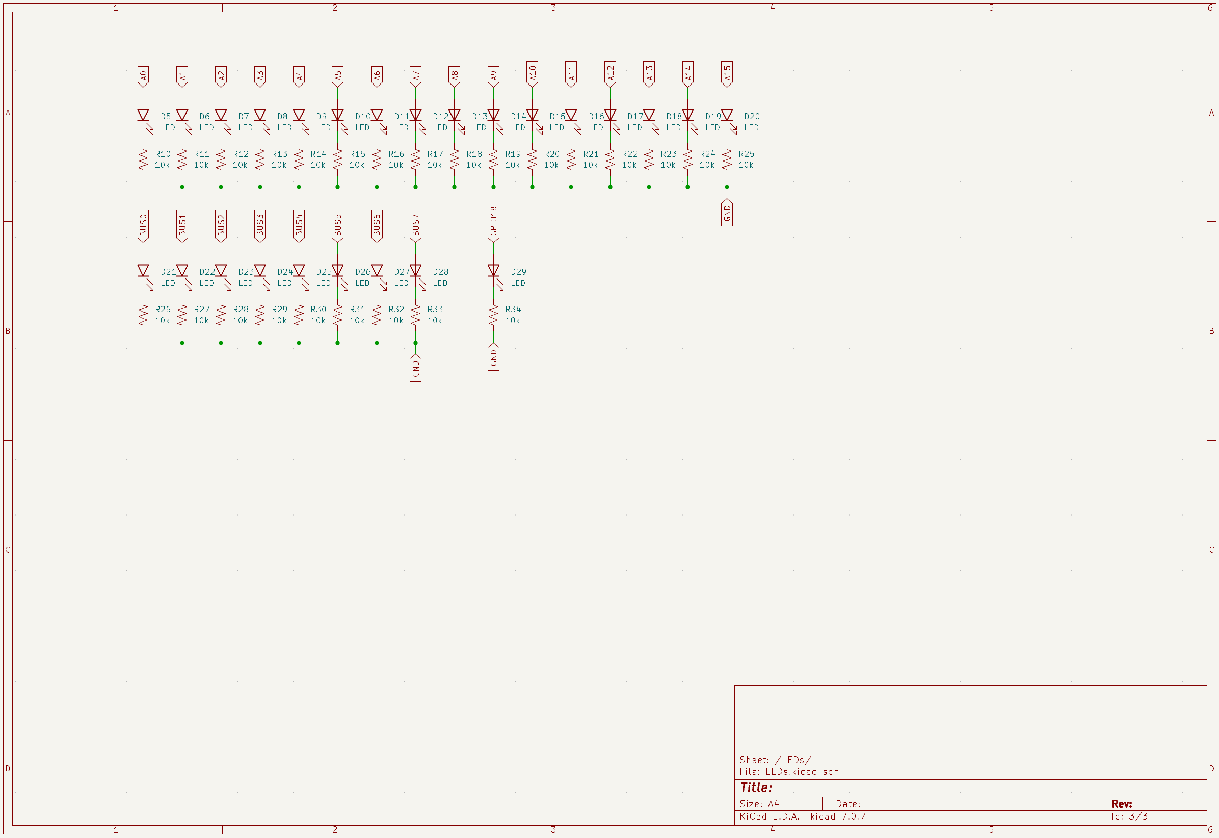
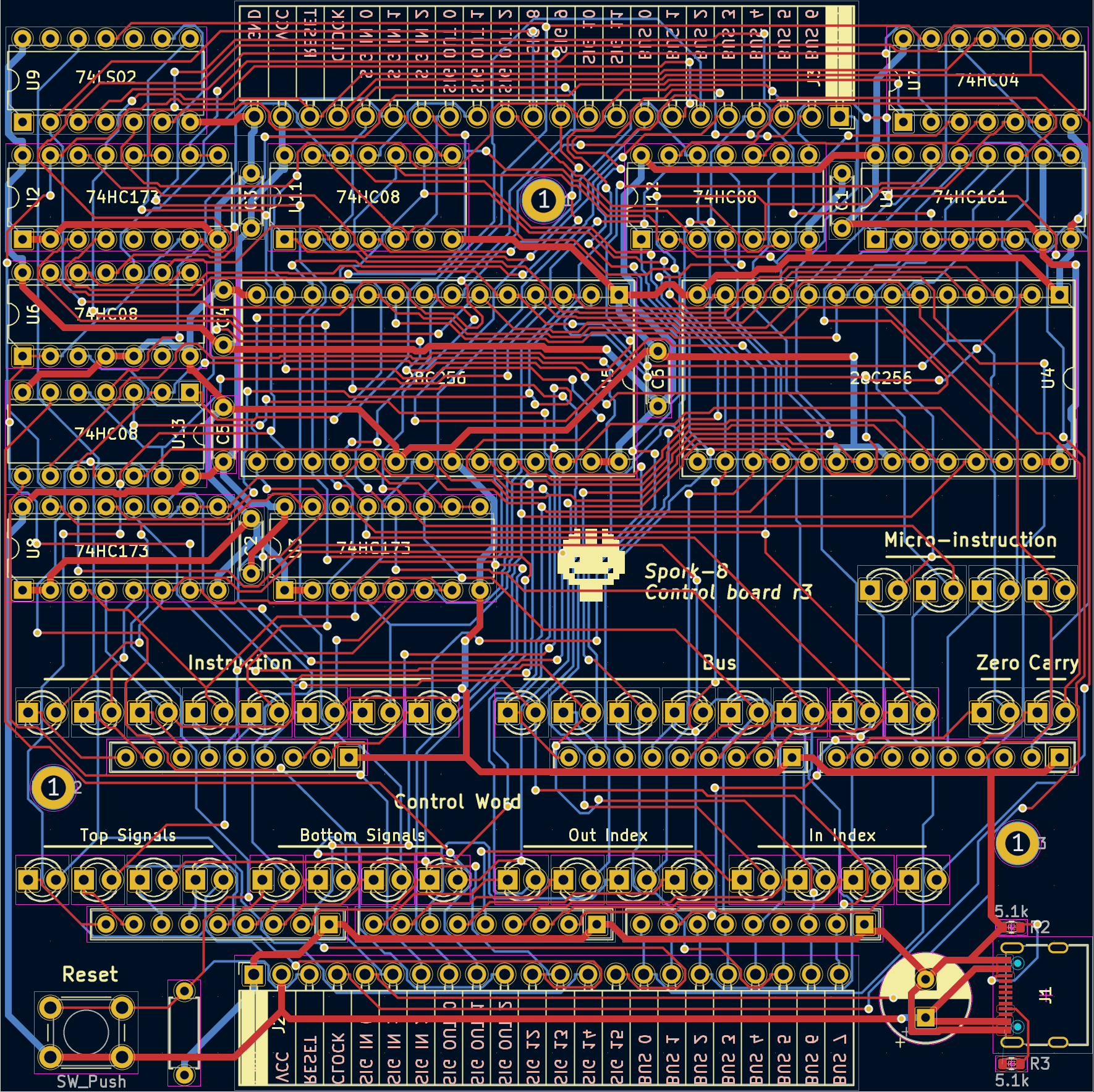
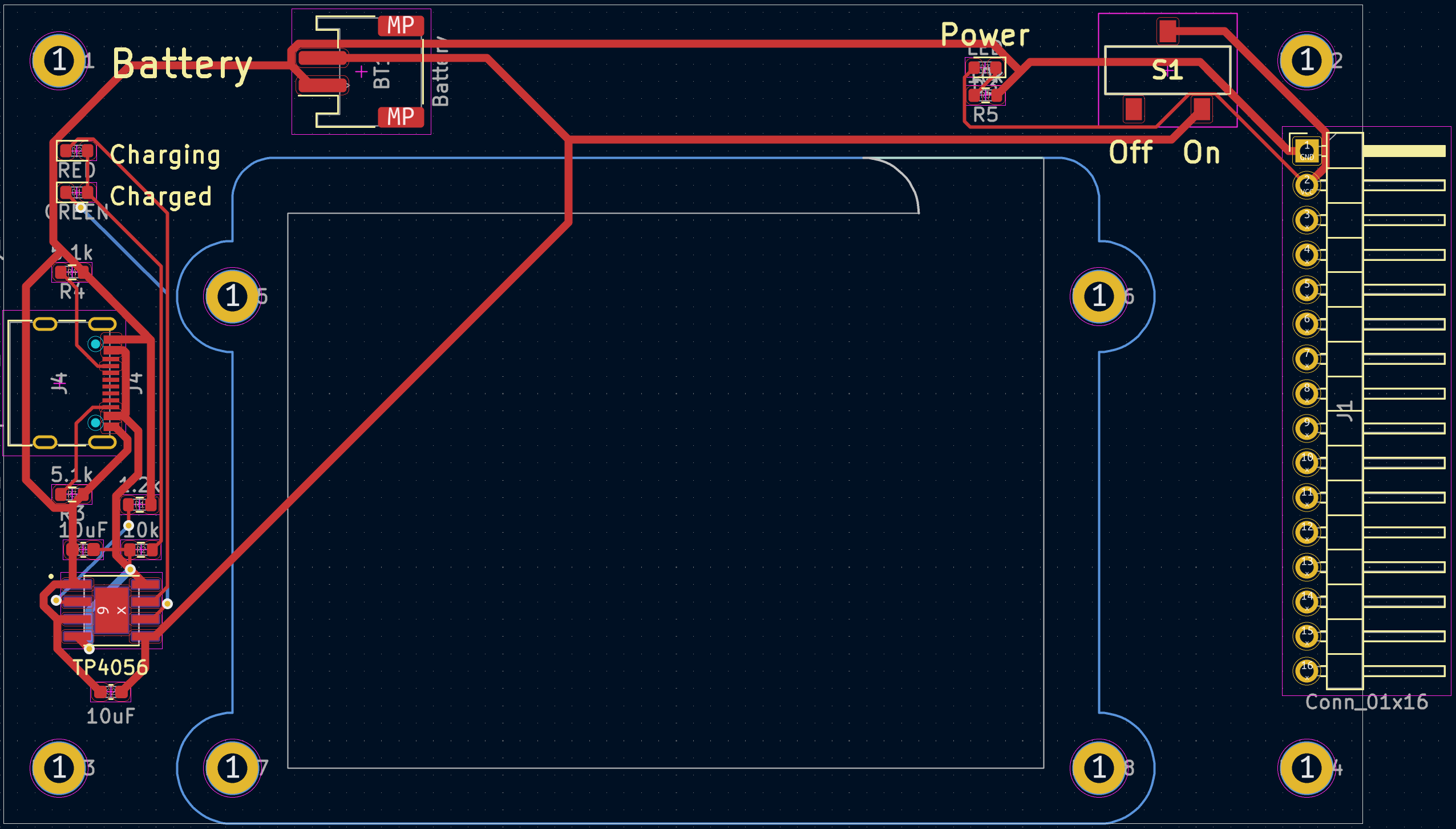
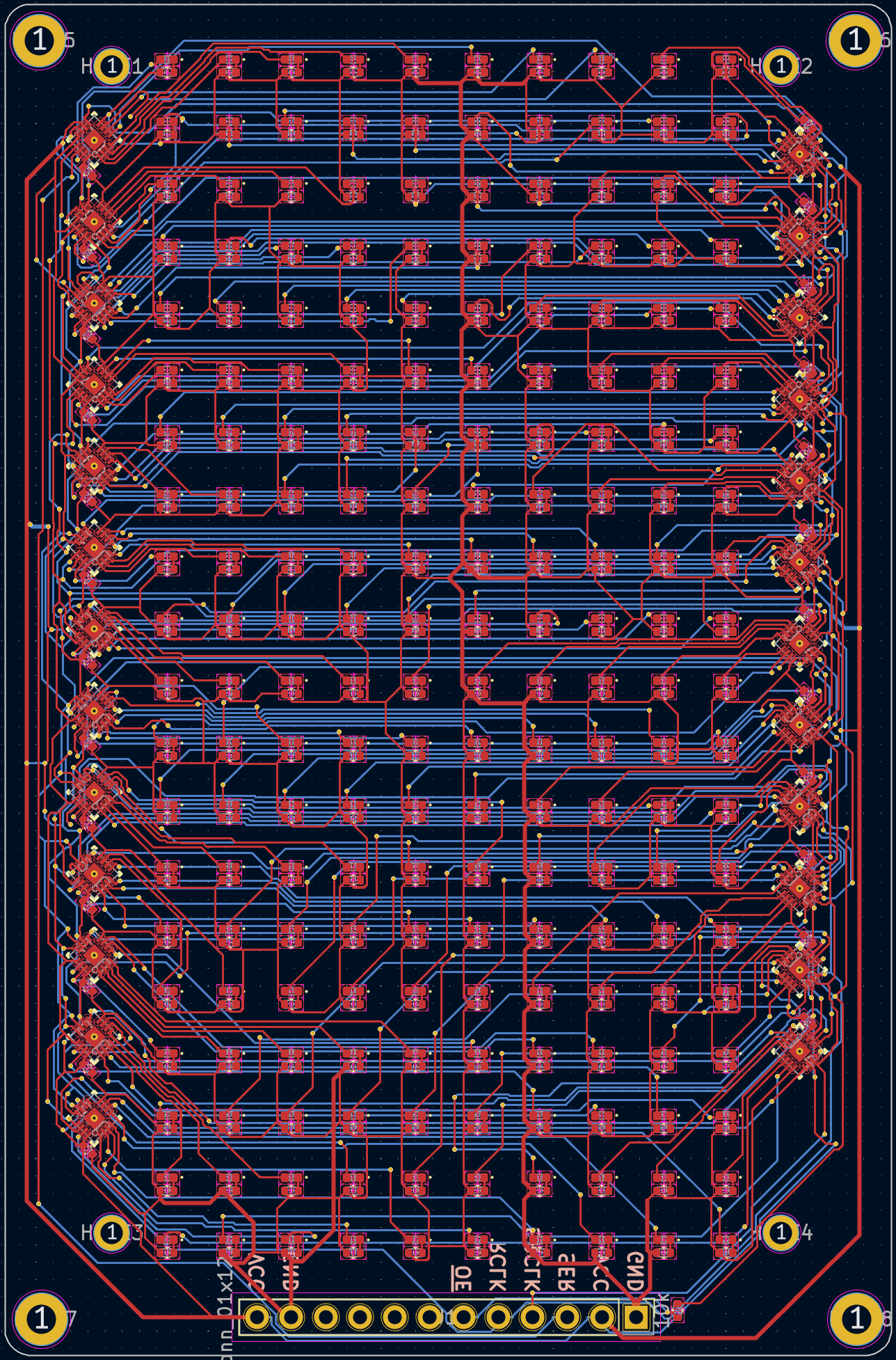
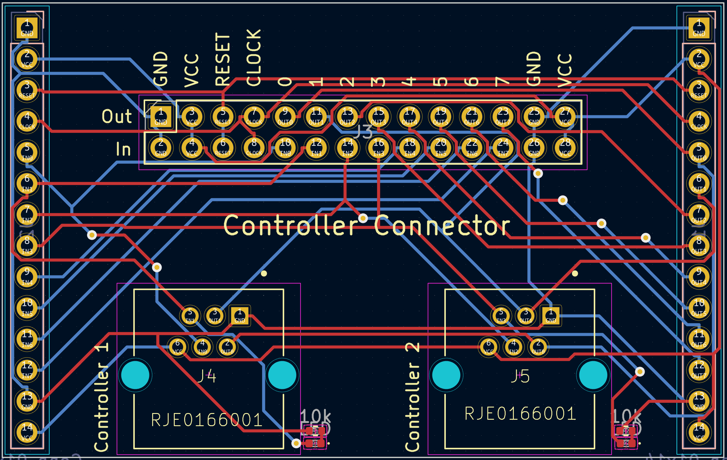
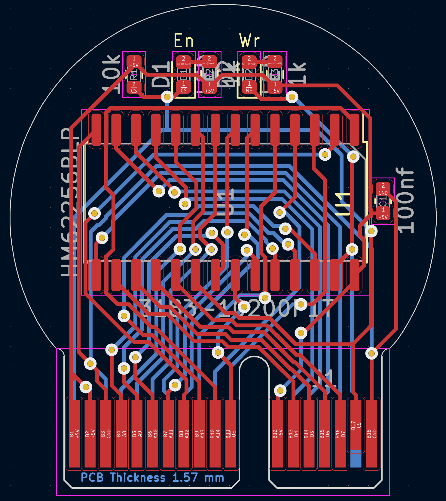
| Qty | Value | Footprint | References |
|---|---|---|---|
| 27 | 10k | Resistor_SMD:R_0603_1608Metric | R2, R10, R11, R12, R13, R14, R15, R16, R17, R18, R19, R20, R21, R22, R23, R24 +11 |
| 25 | LED | LED_SMD:LED_0603_1608Metric | D10, D11, D12, D13, D14, D15, D16, D17, D18, D19, D20, D21, D22, D23, D24, D25 +9 |
| 12 | 10k | Resistor_SMD:R_0402_1005Metric | R35, R36, R37, R38, R39, R40, R41, R42, R43, R44, R45, R46 |
| 6 | 0.1uF | Capacitor_SMD:C_0603_1608Metric | C8, C9, C10, C11, C12, C13 |
| 5 | 4.7uF | Capacitor_SMD:C_0402_1005Metric | C1, C2, C3, C4, C6 |
| 4 | 74HC161 | Package_SO:SOIC-16_3.9x9.9mm_P1.27mm | U4, U5, U6, U7 |
| 4 | MountingHole_2.2mm_M2_DIN965_Pad | MountingHole:MountingHole_2.2mm_M2_DIN965_Pad | HOLE1, HOLE2, HOLE3, HOLE4 |
| 2 | 0.1uF | Capacitor_SMD:C_0402_1005Metric | C5, C7 |
| 2 | 47k | Resistor_SMD:R_0603_1608Metric | R1, R9 |
| 2 | 5.1k | Resistor_SMD:R_0603_1608Metric | R3, R4 |
| 2 | Conn_01x22 | Connector_PinSocket_2.54mm:PinSocket_1x22_P2.54mm_Horizontal | J2, J3 |
| 2 | GREEN | LED_SMD:LED_0603_1608Metric | D1, D4 |
| 1 | 1k | Resistor_SMD:R_0402_1005Metric | R7 |
| 1 | 22.1k | Resistor_SMD:R_0402_1005Metric | R5 |
| 1 | 3183-10200P1T | updated_libs:318310200P1T | J5 |
| 1 | 47.5k | Resistor_SMD:R_0402_1005Metric | R6 |
| 1 | ATMEGA328-AU | Package_QFP:TQFP-32_7x7mm_P0.8mm | U1 |
| 1 | CONTINUE | TS-1088-AR02016:SW_TS-1088-AR02016 | SW4 |
| 1 | CP2102N-Axx-xQFN24 | Package_DFN_QFN:QFN-24-1EP_4x4mm_P0.5mm_EP2.6x2.6mm | U2 |
| 1 | Conn_01x16 | Connector_PinHeader_2.54mm:PinHeader_1x16_P2.54mm_Horizontal | J4 |
| 1 | Conn_02x04_Odd_Even | Connector_PinHeader_2.54mm:PinHeader_2x04_P2.54mm_Vertical | J6 |
| 1 | HM62256BLP | Package_DIP:DIP-28_W15.24mm_Socket | U3 |
| 1 | PAUSE | TS-1088-AR02016:SW_TS-1088-AR02016 | SW2 |
| 1 | RED | LED_SMD:LED_0603_1608Metric | D3 |
| 1 | RESET | TS-1088-AR02016:SW_TS-1088-AR02016 | SW1 |
| 1 | Resonator | updated_libs:OSC_CSTCE16M0V53-R0 | 16MHz1 |
| 1 | SP0503BAHT | Package_TO_SOT_SMD:SOT-143 | D2 |
| 1 | STEP | TS-1088-AR02016:SW_TS-1088-AR02016 | SW3 |
| 1 | USB_C_Receptacle_USB2.0 | updated_libs:USB_C_Receptacle_G-Switch_GT-USB-7010ASV | J1 |
It measures 99.6 × 59.9 mm and has 2 copper layers, 1.6 mm thick.
110 parts, built around the ATMEGA328-AU, 74HC161S, HM62256BLP-7 and 3183-10200P1T. The full list of its parts is on this page, with links to each part's symbol and footprint where PCBKit's library has them.
From the benanderman/spork-8 repository on GitHub, at the commit this page was made from: the board is Programmer/Programmer.kicad_pcb. PCBKit opens the board in the browser, with nothing to install.
Its repository publishes it under the MIT licence: you may reuse it on that licence's terms (keep the author's notice, and for a copyleft licence share your changes alike).
benanderman/spork-8
An 8-bit CPU, made with TTL chips on custom, modular PCBs. Includes board designs, and Arduino code to program its instruction set and programs.

benanderman/spork-8
An 8-bit CPU, made with TTL chips on custom, modular PCBs. Includes board designs, and Arduino code to program its instruction set and programs.

benanderman/spork-8
An 8-bit CPU, made with TTL chips on custom, modular PCBs. Includes board designs, and Arduino code to program its instruction set and programs.

benanderman/spork-8
An 8-bit CPU, made with TTL chips on custom, modular PCBs. Includes board designs, and Arduino code to program its instruction set and programs.

benanderman/spork-8
An 8-bit CPU, made with TTL chips on custom, modular PCBs. Includes board designs, and Arduino code to program its instruction set and programs.

benanderman/spork-8
An 8-bit CPU, made with TTL chips on custom, modular PCBs. Includes board designs, and Arduino code to program its instruction set and programs.

benanderman/spork-8
An 8-bit CPU, made with TTL chips on custom, modular PCBs. Includes board designs, and Arduino code to program its instruction set and programs.

benanderman/spork-8
An 8-bit CPU, made with TTL chips on custom, modular PCBs. Includes board designs, and Arduino code to program its instruction set and programs.

benanderman/spork-8
An 8-bit CPU, made with TTL chips on custom, modular PCBs. Includes board designs, and Arduino code to program its instruction set and programs.

benanderman/spork-8
An 8-bit CPU, made with TTL chips on custom, modular PCBs. Includes board designs, and Arduino code to program its instruction set and programs.

benanderman/spork-8
An 8-bit CPU, made with TTL chips on custom, modular PCBs. Includes board designs, and Arduino code to program its instruction set and programs.

benanderman/spork-8
An 8-bit CPU, made with TTL chips on custom, modular PCBs. Includes board designs, and Arduino code to program its instruction set and programs.


slu4coder/Minimal-64x4-Home-Computer
My DIY TTL home computer with VGA and PS/2 and 4x the processing power of a Commodore C64 or Apple II.

slu4coder/Minimal-UART-Computer-1-2
Legacy: Version 1 and 2 of my TTL-only CPU featuring UART I/O, an expansion port, 512KB SSD at up to 10MHz clock speed

slu4coder/Minimal-64-Home-Computer
Legacy: Full TTL-only home computer with VGA and PS/2 and twice the processing power of a Commodore 64

RadioThermal/RadioThermal_Soldering_OSHW
Open Source Hardware 470KHz Induction Soldering Iron

slu4coder/Minimal-UART-Computer-3
Version 3 of my educational DIY TTL computer built around a UART serial interface - now with blinkenlights!

emeargt/nes-cnrom
KiCad project for NES-CN-ROM-256-05 cartridge schematic and PCB
