2 layers100 × 61.4 mm
Cart
digilogistist/The-Open-Source-USB-NES-Project
USB-NES and NES-FASTGFX product engineering repository
38 parts24CC0-1.0

 emeargt/nes-cnrom31
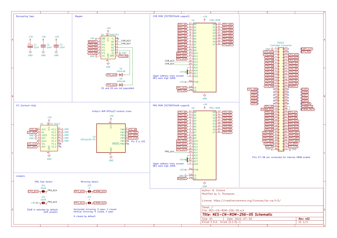
KiCad project for NES-CN-ROM-256-05 cartridge schematic and PCB
NES CN ROM-256-05 is an open-source printed circuit board by emeargt, from the emeargt/nes-cnrom repository on GitHub, published under the CC-BY-SA-4.0 licence. It is a 2-layer board of 99.7 × 63.9 mm with 17 parts on 61 nets, routed with 380 tracks and 69 vias.
It is built around the ATTINY13A-PU and 74HC161S. Its parts include 4 ICs, 3 capacitors and 2 diodes. It belongs with the retro computing and games boards and the AVR (ATmega, ATtiny) boards of this library.


This repository contains a KiCad project for a NES-CN-ROM-256-05 cartridge pcb.
Original NES-CN-ROM-256-05 schematic is from N. Schenk's NES repo. The schematic was modified to include currently available parts and their associated footprints.
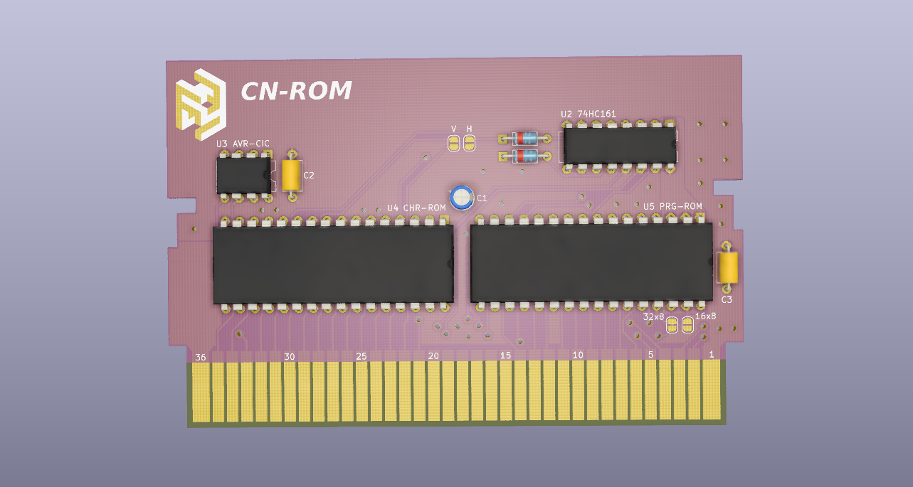
The board matches the dimensions of the original and will idealy fit in standard or reproduction shells. A list of parts to populate the board can be found in the bom directory.
There is a basic build guide that provides some tips and resources for bringing up a board.
v02 was designed to support the SST39SF0x0A series of 32 DIP flash chips. However, the AT27CxxxR series of 28 DIP EPROMs have a very similar pinout and should work on the board by mapping pin 1 of the EPROM to pin 3 of the 32 DIP footprint. Other 28 DIP memory chips may work as well, but their pinouts should be compared to that of the SST39SF0x0A to be certain.
| Top | Bottom |
|---|---|
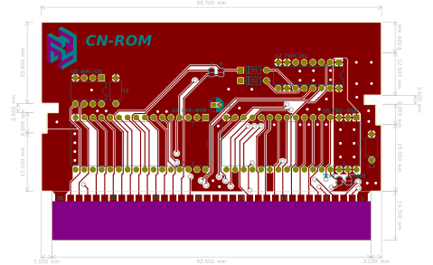 | 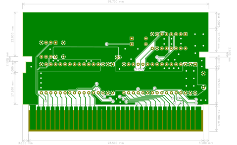 |
Board render (front):
| Qty | Value | Footprint | References |
|---|---|---|---|
| 2 | 10nF | Capacitor_THT:C_Axial_L5.1mm_D3.1mm_P7.50mm_Horizontal | C2, C3 |
| 2 | 1N4148 | Diode_THT:D_DO-35_SOD27_P7.62mm_Horizontal | D1, D2 |
| 1 | 16x8 | Jumper:SolderJumper-2_P1.3mm_Open_RoundedPad1.0x1.5mm | JP2 |
| 1 | 22uF | Capacitor_THT:CP_Radial_D4.0mm_P1.50mm | C1 |
| 1 | 32x8 | Jumper:SolderJumper-2_P1.3mm_Bridged_RoundedPad1.0x1.5mm | JP1 |
| 1 | 74HC161 | Package_DIP:DIP-16_W7.62mm | U2 |
| 1 | ATtiny13A-PU | Package_DIP:DIP-8_W7.62mm | U3 |
| 1 | CHR-ROM | Package_DIP:DIP-32_W15.24mm | U4 |
| 1 | Cartridge Connector | nes_cartridge:cartridge_edge_72 | EDGE1 |
| 1 | H | Jumper:SolderJumper-2_P1.3mm_Open_RoundedPad1.0x1.5mm | JP3 |
| 1 | LOGO | logo:flash_negative_logo | G2 |
| 1 | LOGO | logo:cnrom_text | G3 |
| 1 | LOGO | logo:flash_logo | G1 |
| 1 | PRG-ROM | Package_DIP:DIP-32_W15.24mm | U5 |
| 1 | V | Jumper:SolderJumper-2_P1.3mm_Open_RoundedPad1.0x1.5mm | JP4 |
digilogistist/The-Open-Source-USB-NES-Project
USB-NES and NES-FASTGFX product engineering repository


WiiMake/picones
In the last 40 years, technology has advanced to the point were what used to be done in hardware can now be done in software. This project uses an rp2350 to emulate a ROM chip on an NES Cartridge.


bazsimarkus/a277d-led-tachometer
An analog LED tachometer controlled by an East German A277D chip (clone of UAA180), featuring an integrated ATtiny13A-based digital ignition pulse generator for testing.

CesarOtoniel/charlieplexedHeart
Charlieplexed LED sequencer with the shape of a heart. Intended to be mounted on wired LED sign and not on the PCB.
It measures 99.7 × 63.9 mm and has 2 copper layers, 1.6 mm thick.
17 parts, built around the ATTINY13A-PU and 74HC161S. The full list of its parts is on this page, with links to each part's symbol and footprint where PCBKit's library has them.
From the emeargt/nes-cnrom repository on GitHub, at the commit this page was made from: the board is NES-CN-ROM-256-05.kicad_pcb. PCBKit opens the board in the browser, with nothing to install.
Its repository publishes it under the CC-BY-SA-4.0 licence: you may reuse it on that licence's terms (keep the author's notice, and for a copyleft licence share your changes alike).