
4 layers62.1 × 83.8 mm
Ss main board
loopj/short-stack
World's Smallest Nintendo Wii, using a trimmed motherboard and custom stacked PCBs
69 parts804
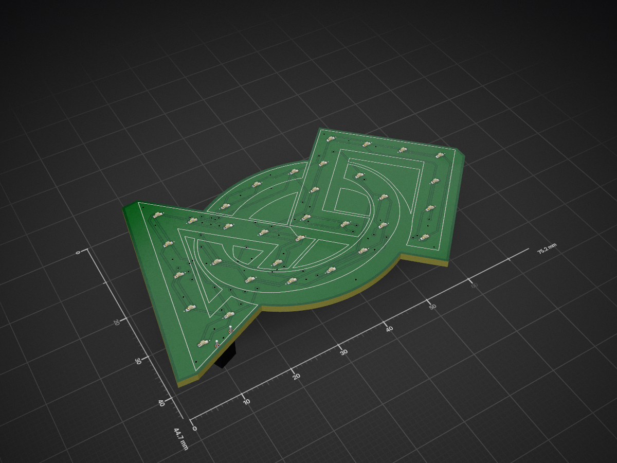
 bckircher/ATtinyBadge
Wearable LED badge based on an ATtiny1616 microcontroller
ATtinyBadge RevA is an open-source printed circuit board by bckircher, from the bckircher/ATtinyBadge repository on GitHub, published under the BSD-3-Clause licence. It is a 2-layer board of 75.2 × 44.7 mm with 50 parts on 32 nets, routed with 329 tracks and 70 vias.
It is built around the ATTINY1616-MN. Its parts include 33 diodes, 12 resistors, 1 capacitor, 1 IC and 1 switch. It belongs with the AVR (ATmega, ATtiny) boards of this library.
Copyright © 2026 Brian Kircher
Open Source Software: you can modify and/or share it under the terms of the BSD license file in the root directory of this project.
This project is a small (75.2 mm by 44.7 mm) circuit board in the shape of the FIRST® logo. Each symbol in the logo is painted the appropriate color, and has a set of 11 LEDs (of matching color). It is powered by a single CR2032 coin cell battery, which provides a typical run time of N hours.
[animated gif image]
Once turned on, a random, short animation is played one a minute. Once in a while, a special, longer animation is played instead. Pressing the button causes another animation to be played without further delay (canceling the one minute delay). Holding the button for two seconds turns the badge off, placing it into an extremely low power mode. This also happens after the badge has been running for eight hours (so it doesn't run continously until the battery is fully depleted). When off, pressing the button turns it back on and repeats the process.
Full details of the design, development, and construction process can be found here.
The board is designed using KiCad, with the design
files and resulting gerbers provided in the hardware directory. It uses 6/6
design rules, with a 12 mil minimum drill size, so it should be easily
manufactured by any number of prototype board shops (so long as they are able
to make the very odd, non-rectangular shape of the board). My personal
preference is PCBWay.
The components are populated by hand (since the board has components on both sides, the hot plate technique only works for one side!), and the PCB is then hand painted to match the FIRST logo and protected with a coating of a spray shellac. Safety pins like these are soldered to the exposed pad at the top of the back and used to attach the badge to a shirt/lapel/etc.
The firmware that runs on the ATtiny1616 is written using
TinyGo, and is provided in the firmware directory.
One space saving optimization that could be done is a custom target that does
not enable the timing services that are a standard part of the TinyGo targets;
that timer is simply disabled after the application starts, making all the
timer setup code effectively "dead code" (even though it still exists and
runs).
The firmware can also be built and run natively (using normal Go) in order to develop, debug, and test new animations. It uses ANSI control sequences with the command line terminal to generate an ASCII-art simulation of the LED array, with the LEDs "lighting up" as defined by the animation (with the same timing).
FIRST® is a trademark of For Inspiration and Recognition of Science and Technology (FIRST), which does not sponsor, authorize, or endorse this application.
It is very much hoped that this does not ruffly any feathers at FIRST, especially since the color palette could not be exactly adhered to with off-the-shelf acrylic paints.
| Qty | Value | Footprint | References |
|---|---|---|---|
| 33 | LED | LED_SMD:LED_0402_1005Metric_Pad0.77x0.64mm_HandSolder | D1, D2, D10, D11, D12, D13, D14, D15, D16, D17, D18, D19, D20, D21, D22, D23 +17 |
| 12 | R | Resistor_SMD:R_0402_1005Metric_Pad0.72x0.64mm_HandSolder | R1, R2, R3, R4, R5, R6, R7, R8, R9, R10, R11, R12 |
| 1 | 10 uF | Capacitor_SMD:C_0402_1005Metric_Pad0.74x0.62mm_HandSolder | C1 |
| 1 | ATtiny1616-M | Package_DFN_QFN:VQFN-20-1EP_3x3mm_P0.4mm_EP1.7x1.7mm | U1 |
| 1 | Battery_Cell | Battery:BatteryHolder_Keystone_1058_1x2032 | BT1 |
| 1 | SW_Push | bck:SWT0005 | SW1 |
| 1 | TestPoint_2Pole | Resistor_SMD:R_2512_6332Metric_Pad1.40x3.35mm_HandSolder | TP1 |
loopj/short-stack
World's Smallest Nintendo Wii, using a trimmed motherboard and custom stacked PCBs


kieraneglin/hexagon-art
A passive breakout board: two lever-terminal inputs, three JST XH outputs, all six conductors (RX bus, two spares, +12V, GND, +5V) paralleled straight across. No active components, no regulation, nothing to configure.

engineerbo/flashlight-dev-hw
This repository contains design files for the development board for a flashlight boost driver. The test firmware can be found in the firmware repository.

hojadurdy/Flux_Capacitor_Micro
A tiny (36mm x 29mm) pin badge and keychain PCB version of Flux Capacitor featuring 25 animated LEDs that animate to create the “fluxxing” effect.


It measures 75.2 × 44.7 mm and has 2 copper layers, 1.6 mm thick.
50 parts, built around the ATTINY1616-MN. The full list of its parts is on this page, with links to each part's symbol and footprint where PCBKit's library has them.
From the bckircher/ATtinyBadge repository on GitHub, at the commit this page was made from: the board is hardware/RevA/ATtinyBadge_RevA.kicad_pcb and its schematic hardware/RevA/ATtinyBadge_RevA.kicad_sch. PCBKit opens the board in the browser, with nothing to install.
Its repository publishes it under the BSD-3-Clause licence: you may reuse it on that licence's terms (keep the author's notice, and for a copyleft licence share your changes alike).