
2 layers67.3 × 74.9 mm

 badges4dotcom/bsidesperth2025badge5
Instructions on how to assemble the physical badge can be found here
Bsides perth 2025 is an open-source printed circuit board by badges4dotcom, from the badges4dotcom/bsidesperth2025badge repository on GitHub. It is a 2-layer board of 68.7 × 100 mm with 15 parts on 30 nets, routed with 162 tracks and 0 vias.
It is built around the ESP32-DEVKITM-1. Its parts include 4 resistors, 4 switches, 3 connectors and 1 IC. It belongs with the ESP32 boards of this library.
Instructions on how to assemble the physical badge can be found here
If a re-download of the physical badge is required, follow these instructions. This will be required if you wish to attempt the online challenges (see Known Issues below).
| Qty | Item | Link | Alternative Link |
|---|---|---|---|
| 4 | 6x6x6mm Push Button Tactile Switch | Link | |
| 4 | 10k 1/4W 1% Metal Film Resistor | Link | |
| 1 | 1x4 2.54mm Male Header Pin Connector | Link | |
| 1 | 1x8 2.54mm Female Header Pin Connector | Link | Link |
| 1 | 1x4 2.54mm Female Header Pin Connector | Link | Link |
| 2 | 1x15 2.54mm Female Header Pin Connector | Link | Link |
| 1 | 2x3 2.54mm Femal Header Pin Connector | Link | |
| 1 | ESP32 DOIT DevKit v1 - 30Pin | Link | |
| 1 | 1.8" LCD TFT Display | Link |
The virtual badge can be accessed here: https://badge.bsidesperth.com.au/
The code for the Virtual Badge code can be found in this repository under "VirtualBadge".
The virtual badge does not support "Online Challenges", but does contain hidden features such as a second episode, cheats, and an easter egg.
The virtual badge now supports keyboard inputs. The four buttons are mapped to W [Up], S [Down], A [Left/A], and D [Right/B]. Once a keyboard input is used, the symbols used in the sequence game change to U = UP, D = DOWN, L = LEFT, R = RIGHT. Thanks again to Matt for the suggestion and the code snippet for this feature.
There is a basic template for an Arduino program under the folder "Template". The template demonstrates basic use of the LCD screen, ESP32, and button inputs. The download instructions can be found here.
Code for the Virtual Badge Server (API for Online Challenges) will be made available ~1st November 2025.
A badge holder can be 3D printed using an off-the-shelf 3D printer. Recommended print settings are PLA plastic, 60+% infill, 40mm/s print speed. Some stringing may occur if filament is damp and/or print speed is too high.
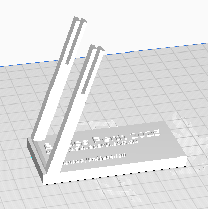
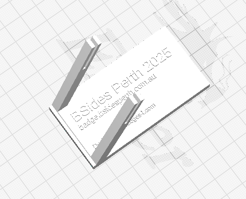
Customisation of the virtual and physical badge are both possible. Extra details can be found here

| Qty | Value | Footprint | References |
|---|---|---|---|
| 4 | 10k | Resistor_THT:R_Axial_DIN0207_L6.3mm_D2.5mm_P10.16mm_Horizontal | R1, R2, R3, R4 |
| 1 | DOWN | Button_Switch_THT:SW_PUSH_6mm_H5mm | SW2 |
| 1 | ESP32_DevKit | bsides_perth_2025:esp32_devkit_v1_doit | U1 |
| 1 | LEFT / A | Button_Switch_THT:SW_PUSH_6mm_H5mm | SW4 |
| 1 | LOGO | bsides_perth_2025:bsides_footprint | G*** |
| 1 | LOGO | LOGO | G*** |
| 1 | RIGHT / B | Button_Switch_THT:SW_PUSH_6mm_H5mm | SW3 |
| 1 | SAO v1.69bis | Connector_PinHeader_2.54mm:PinHeader_2x03_P2.54mm_Vertical | J3 |
| 1 | SD Card (Optional) | Connector_PinHeader_2.54mm:PinHeader_1x04_P2.54mm_Vertical | J2 |
| 1 | TFT Display | Connector_PinHeader_2.54mm:PinHeader_1x08_P2.54mm_Vertical | J1 |
| 1 | UP | Button_Switch_THT:SW_PUSH_6mm_H5mm | SW1 |
The 14 most common of 15 parts.
It measures 68.7 × 100 mm and has 2 copper layers, 1.6 mm thick.
15 parts, built around the ESP32-DEVKITM-1. The full list of its parts is on this page, with links to each part's symbol and footprint where PCBKit's library has them.
From the badges4dotcom/bsidesperth2025badge repository on GitHub, at the commit this page was made from: the board is PCBDesign/bsides_perth_2025/bsides_perth_2025.kicad_pcb and its schematic PCBDesign/bsides_perth_2025/bsides_perth_2025.kicad_sch. PCBKit opens the board in the browser, with nothing to install.
Its repository states no licence, so its author keeps all rights: ask badges4dotcom before reusing the design.


axlan/pcb-map
PCB designs, firmware, and host SW for controlling an interactive map printed onto a PCB board.


ronaldsieber/ESP32SmartBoard_PCB
KiCad project of a Printed Cuircit Board (PCB) for ESP32 with Temperature/Humidity/CO2 Sensors, User LEDs and Buttons

cristianghsandu/edifier-remote
An ESP32 based IR signals translator to use the LG Magic remote to control the volume on an Edifier 2.1 system

Pendu1699/solar-mppt-charge-controller
ESP32-based solar MPPT charge controller, custom PCB, perturb & observe tracking algorithm, logged efficiency test data.

nakujaproject/N3FlightComputer-PCB
Electrical schematics and PCB for N3 flight computer