Skip to the content
PCBKitNew board
2 layers118 × 70 mmESP32SmartBoard PCB, the printed circuit board in 3D

KiCad project of a Printed Cuircit Board (PCB) for ESP32 with Temperature/Humidity/CO2 Sensors, User LEDs and Buttons

Size
118 × 70 mm
Copper layers
2
Thickness
1.6 mm
Parts
36
Nets
45
Pads
111
Tracks, vias
203, 0
Routed
Yes
KiCad
KiCad 5 (file 20171130)
Created
1 Feb 2021
Updated
6 Apr 2021

Overview

ESP32SmartBoard PCB is an open-source printed circuit board by ronaldsieber, from the ronaldsieber/ESP32SmartBoard_PCB repository on GitHub, published under the MIT licence. It is a 2-layer board of 118 × 70 mm with 36 parts on 45 nets, routed with 203 tracks and 0 vias.

It is built around the ESP32-DEVKITM-1, MH-Z19B and DHT22. Its parts include 13 resistors, 10 diodes, 3 ICs, 3 switches and 2 capacitors. It belongs with the sensors and measurement boards and the ESP32 boards of this library.

Main components

3

README

README.md

ESP32SmartBoard_PCB

KiCad project of a Printed Cuircit Board (PCB) for ESP32 with Temperature/Humidity/CO2 Sensors, User LEDs and Buttons.

In the past I've implemented various Smart Projects with the ESP32 on break-out boards. On the one hand, break-out boards are very useful because they make hardware modifications as easy as software changes. On the other hand, it is very cumbersome to build several copies of the same circuit with break-out boards. Furthermore, they are mechanically fragile and not really particularly visually appealing. Therefore they are not very suitable for permanent use in the visible area of living rooms.

For this reason I designed the ESP32SmartBoard_PCB, which combines different projects on a single, professionally producible PCB. This allows now for reproducing multiple copies of a device without great effort and hide them in a small housing if necessary.

Board Features

The ESP32SmartBoard_PCB contains the following components:

  • ESP32 Development Kit
  • DHT22 (combined temperature and humidity sensor)
  • MH-Z19 (CO2 sensor with integrated temperature sensor)
  • 9 freely usable user LEDs (LED0..LED8, arranged in one row and usable as a LED Bar)
  • 3 freely usable user Buttons (KEY0, KEY1, BLE_CFG)
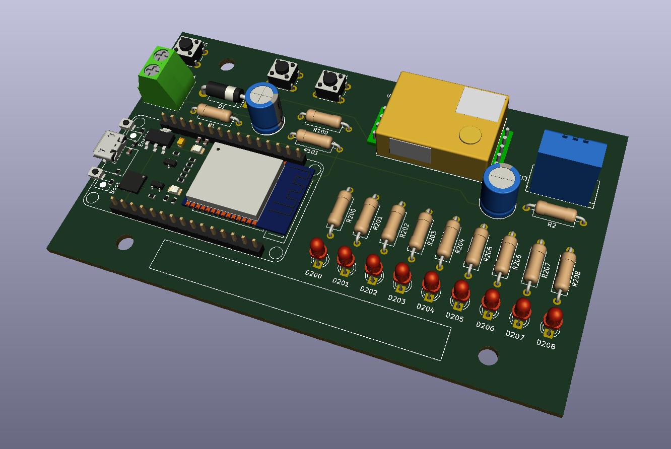
[kicad_3d_model]

Board Description

The ESP32SmartBoard_PCB is a two-layer Printed Circuit Board (PCB), assembled on one side and only uses THT components (Through Hole Technology) that are very easy to solder. It can therefore be used very easily also by students and hobbyists.

The values of all components are specified in the Schematic.

The PCB size and the positions of the mounting holes allow installation in the plastic universal housing of 135 x 95 x 45 mm (article number 523117). This polystyrene housing (EPS) can be easily processed mechanically (e.g. cut out a viewing window for the LED Bar). It is available from various providers on the Internet.
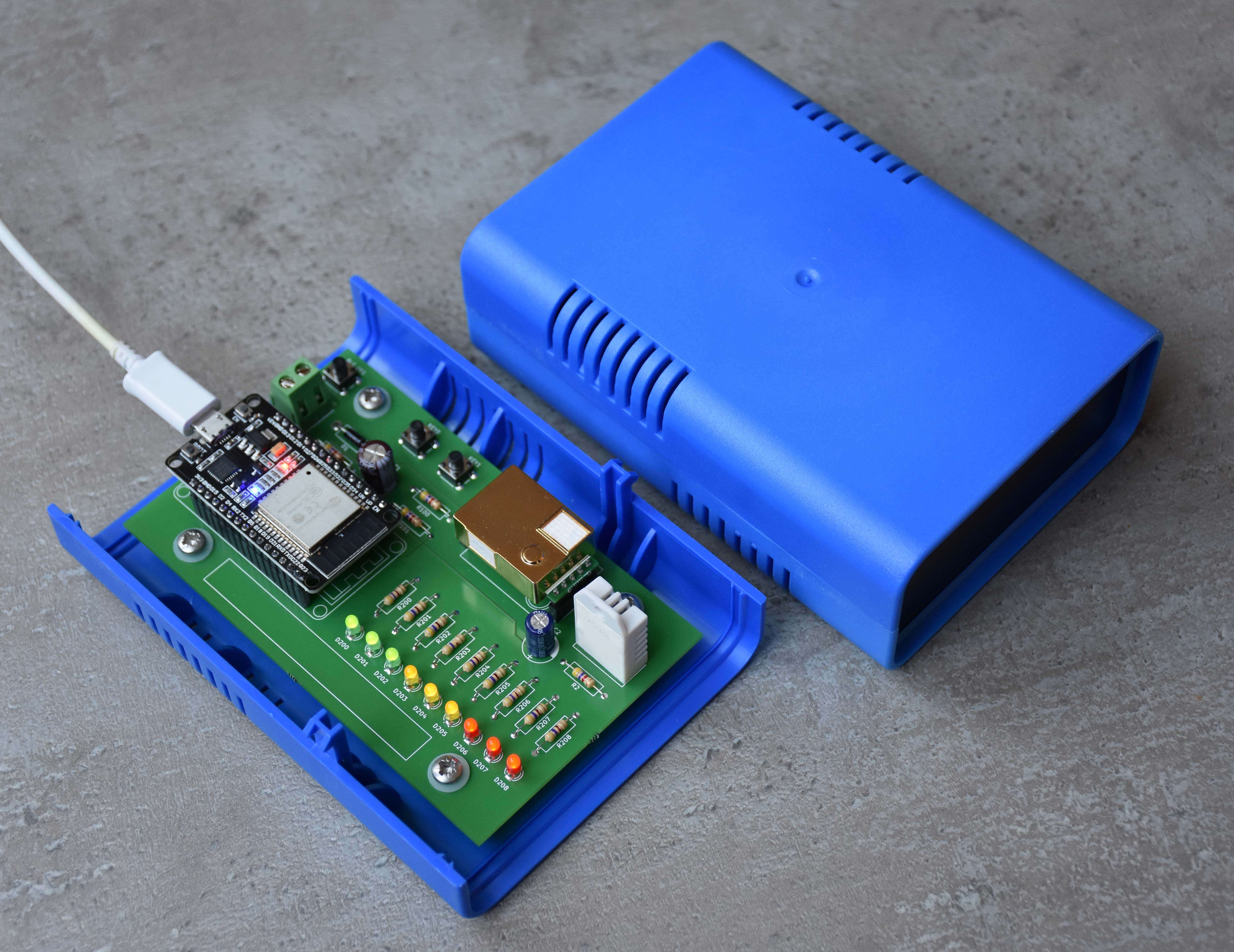
[ESP32SmartBoard_OpenFrame_with_Box]

By searching in the Internet, several PCB manufacturers can be found who are able to directly import the KiCad layout file ESP32SmartBoard_PCB.kicad_pcb. The PCBs with silkscreen (assembly printing) on the top are then sent by post after a few days.

Power Supply

There are following options for the power supply of the board:

  • Via USB connection of the ESP32 Development Kit (in this case Pin15/Vin of the ESP32DevKit acts as an output and supplies the rest of the circuit)
  • Supply of 5 ... 6VDC to connector J1 (in this case the rest of the board supplies the ESP32DevKit and Pin15/Vin acts as an input)

Commissioning

With the Arduino sketch from the ESP32SmartBoard_IoCheck repository, all components of the board can be checked for correct function after assembly. The sketch is also a good starting point for new software projects based on this board.

Schematic Symbols, Footprints and 3D Models

Not all schematic symbols, footprints and 3D models required for ESP32SmartBoard_PCB are contained in the native installed KiCad library. External_KiCad_Parts.txt lists the additional components and their download links.

Practice Notes

  • The user LEDs are arranged in one row and can be used as a LED Bar. The colors of the LEDs should be selected according to the respective application. For example, to show the CO2 level in the form of a scale, the following grouping is suitable:

    • LED0..LED2: green = excellent
    • LED3..LED5: yellow = acceptable
    • LED6..LED8: red = critical
  • It seems that there are several versions of the ESP32 Development Kit and the MH-Z19 CO2 sensor with pins of different widths. In my components, the diameter of the connection pins are larger than the diameter of the soldering pads in the footprint. This prevented me from soldering the components directly onto the board. However, I was able to solve the problem by using Pin Headers (see image above). The solder connections of the Pin Headers are small enough for the solder pads and the ESP32 Development Kit and MH-Z19 CO2 sensor can be easily plugged in.

Software Projects for the ESP32SmartBoard

Parts

36
QtyValueFootprintReferences
9470RResistors_THT:R_Axial_DIN0309_L9.0mm_D3.2mm_P12.70mm_HorizontalR200, R201, R202, R203, R204, R205, R206, R207, R208
44k7Resistors_THT:R_Axial_DIN0309_L9.0mm_D3.2mm_P12.70mm_HorizontalR1, R2, R100, R101
1100µFCapacitors_THT:CP_Radial_D8.0mm_P3.50mmC1
11N4001Diodes_THT:D_5W_P12.70mm_HorizontalD1
147µFCapacitors_THT:CP_Radial_D8.0mm_P3.50mmC2
1BLE_CFGButtons_Switches_THT:SW_PUSH_6mm_h5mmSW1
1DHT22Sensors:DHT22_Temperature_HumidityU3
1ESP32_DevKitesp32_devkit_v1_doit:esp32_devkit_v1_doitU1
1KEY0Buttons_Switches_THT:SW_PUSH_6mm_h5mmSW100
1KEY1Buttons_Switches_THT:SW_PUSH_6mm_h5mmSW101
1LED0LEDs:LED_D3.0mmD200
1LED1LEDs:LED_D3.0mmD201
1LED2LEDs:LED_D3.0mmD202
1LED3LEDs:LED_D3.0mmD203
1LED4LEDs:LED_D3.0mmD204
1LED5LEDs:LED_D3.0mmD205
1LED6LEDs:LED_D3.0mmD206
1LED7LEDs:LED_D3.0mmD207
1LED8LEDs:LED_D3.0mmD208
1MH-Z19Bmh-z19b:Winsen_MH-Z19BU2
1VinTerminalBlocks_Phoenix:TerminalBlock_Phoenix_MKDS1.5-2polJ1

The 32 most common of 36 parts.

Questions

How big is the ESP32SmartBoard PCB PCB?

It measures 118 × 70 mm and has 2 copper layers, 1.6 mm thick.

What parts does the ESP32SmartBoard PCB use?

36 parts, built around the ESP32-DEVKITM-1, MH-Z19B and DHT22. The full list of its parts is on this page, with links to each part's symbol and footprint where PCBKit's library has them.

Where can I download the ESP32SmartBoard PCB KiCad files?

From the ronaldsieber/ESP32SmartBoard_PCB repository on GitHub, at the commit this page was made from: the board is ESP32SmartBoard_PCB/ESP32SmartBoard_PCB.kicad_pcb. PCBKit opens the board in the browser, with nothing to install.

Can I use the ESP32SmartBoard PCB design in my own project?

Its repository publishes it under the MIT licence: you may reuse it on that licence's terms (keep the author's notice, and for a copyleft licence share your changes alike).

Similar boards

  • 2 layers100 × 100.1 mmDiploma, the printed circuit board in 3D

    Diploma

    t3ry4git/stm32Co2

    A simple CO2 and environmental monitor based on the STM32F103C8 microcontroller. The firmware reads temperature and humidity from a DHT22 sensor, measures CO2 concentration using an MHZ19B module and displays values on…

    62 parts
  • 2 layers169.1 × 252.5 mmAirguard v1, the printed circuit board in 3D

    Airguard v1

    open-lv/air-guard

    Do-it-yourself electronics kit for building an air quality monitor for your school, work and home.

    38 parts7MIT
  • 2 layers110.1 × 38.6 mmEnvironmentalSensors, the printed circuit board in 3D

    EnvironmentalSensors

    strayer/EnvironmentalSensor

    A WiFi environmental sensor based on Tasmota that reports temperature, air pressure, air quality, humidity and CO2 (ppm).

    8 parts4MIT
  • 2 layers79 × 79 mmHm env sensor, the printed circuit board in 3D

    Hm env sensor

    HiMinds/himinds-boosting-innovation-embedded-env-sensor-hw

    HiMinds Open Source Wireless Environmental Sensor HW

    94 parts1Apache-2.0
  • 2 layers94 × 68.6 mmCO2Sensor, the printed circuit board in 3D

    CO2Sensor

    JensFZ/CO2Sensor_PCB

    Added external power suply, leds and a buzzer (all of them are optional)

    18 parts1
  • 2 layers65 × 40 mmIndoor sensor, the printed circuit board in 3D

    Indoor sensor

    Djuke-DIYAudio/indoor-sensor

    Affordable indoor sensor for measuring CO2, temperature, humidity and pressure

    19 parts
  • 2 layers51.6 × 78 mmMHZ19B wemos BM280 pistes 1mm buzz, the printed circuit board in 3D

    MHZ19B wemos BM280 pistes 1mm buzz

    Gonellarro/Sensor-de-CO2

    Building a C02 and wheather station with Wemos D1 mini micro controller, MH Z19B and BM280 sensors

    10 parts
  • 2 layers43 × 63 mmEnv sensor, the printed circuit board in 3D

    Env sensor

    motty-mio2/env_sensor_pcb

    29 parts