
2 layers158.4 × 113.7 mm
Light control
axlan/pcb-map
PCB designs, firmware, and host SW for controlling an interactive map printed onto a PCB board.
4 parts11

 axlan/pcb-map11
PCB designs, firmware, and host SW for controlling an interactive map printed onto a PCB board.
Map board is an open-source printed circuit board by axlan, from the axlan/pcb-map repository on GitHub. It is a 2-layer board of 241.5 × 321.5 mm with 11 parts on 30 nets, routed with 57 tracks and 0 vias.
It is built around the ESP32-DEVKITM-1. Its parts include 3 connectors and 1 IC. It belongs with the lEDs and displays boards and the ESP32 boards of this library.
This project is two related parts. First is the PCB map itself manufactured by PCBWay. This is a PCB art piece that combines a map of the East Bay of California with an LED matrix display. The second part is the software to control the display.
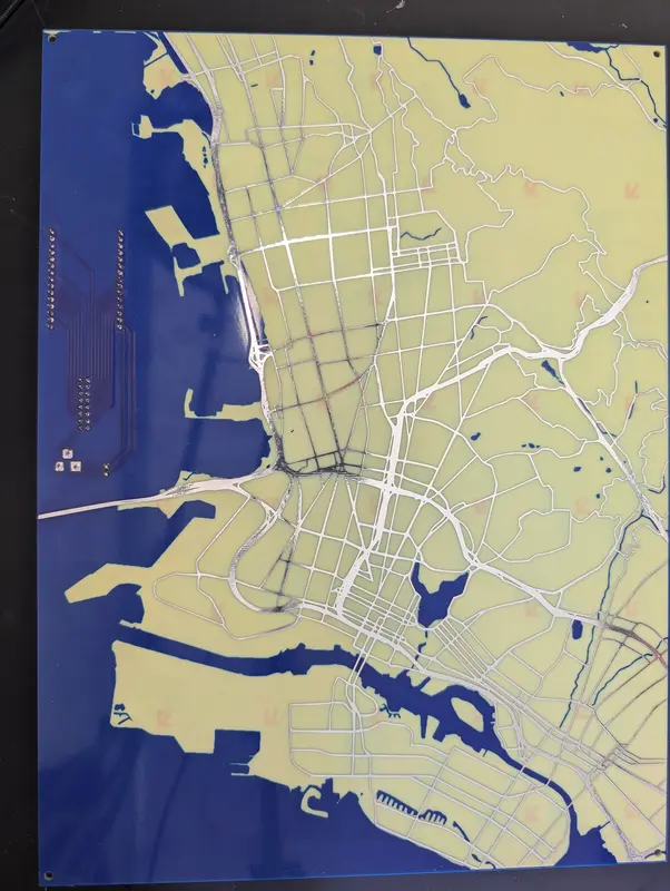
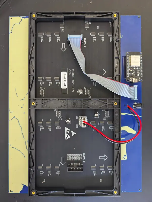
The software is designed to be a fairly flexible controller for a matrix display, and the whole project could easily be used with a map printed on paper instead of a custom PCB.
See https://www.robopenguins.com/pcb-map/ for the design process.
The design files can be found in design/.
The full design is in design/map_board.kicad_pcb, while the schematic for the ESP32 connected the the LED panel was designed in design/wiring_project/map_lights.kicad_pro
I came up with this project in response to an offer from PCBWay to manufacture a board for free in exchange for writing about the experience. The process of submitting the design files was straightforward, and I especially appreciated that their preview system showed the selected solder mask and surface finish colors. The design was flagged for manual review, and I had to confirm that the strange mostly-artistic board layout was intentional. This was entirely reasonable for a PCB that was deliberately designed to be mostly non-functional.
The firmware is located in the firmware/ directory and is built using PlatformIO.
The matrix display that this project was tested with is the: Waveshare RGB Full-Color LED Matrix Panel, 5mm Pitch, 64×32 Pixels
It worked with the ESP32 HUB75 LED MATRIX PANEL DMA Display library out of the box, only needing to modify the mxconfig.clkphase = false.
My display was labeled as P5(2121)-3264-16S-M5 (32x64 1/16 scan) and used the RUC7258D, SM16208SJ, and MW245BC control chips.
To upload the firmware to your ESP32, use the provided helper script:
./scripts/upload_firmware.shThis script uses PlatformIO to build the project and upload it to pcb-map.local (once the device is on your network).
If the device has no saved WiFi credentials, it will start an Access Point named pcb-map-ap. Connect to this AP with your phone or computer to configure your local WiFi settings via the captive portal.
The firmware supports Over-The-Air updates. Once configured on your network, you can re-flash the device wirelessly using PlatformIO's OTA functionality.
The simulator allows you to run the pcb-map logic on your desktop. It renders the LED matrix using SFML and connects to an MQTT broker to receive commands exactly like the hardware would.
The simulator requires SFML, Paho MQTT C++, and OpenSSL. It uses CMake for building:
cd firmware/simulation
mkdir build && cd build
cmake ..
make
./matrix_sim
By default, it attempts to connect to a local MQTT broker at tcp://localhost:1883.
The project includes a suite of Python scripts located in the python/ directory to manage the device and feed it data.
Use uv to manage the Python environment:
uv --directory=python sync
source python/.venv/bin/activate
Install shell tab completion for the commands:
control-server --install-completion
device-setup --install-completion Set up your environment variables (usually via a script like pcb_map_args.sh):
export MQTT_HOSTNAME="your-broker-address"
export MQTT_USE_TLS=1
export MQTT_USERNAME="user"
export MQTT_PASSWORD="pass"
# Used to query the Google Maps API for route information
export GOOGLE_MAPS_API_KEY="your-api-key"
# Used to set specific colors for people when using shared location display
export USER_COLORS_FILE="$HOME/user_colors.json"Define specific colors for people when using shared location display. When specified, only people in this configuration will be displayed.:
{
    "me": [0, 255, 0],
    "Joe Smith": [0, 0, 255],
    "Mary Sue": [255, 0, 0]
}device-setup)find-devices: Discovers the board via mDNS, MQTT, or by scanning for the setup AP.setup-mqtt: Configures the MQTT broker credentials on the device via a local UDP broadcast.clear-wifi-creds: Resets the WiFi settings on the hardware.Here's a rundown of how device configuration works:
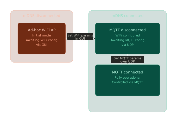
The find-devices command gives the context for what state the device is in.
control-server)display-shared-locations: Fetches shared Google locations and upcoming Google Calendar event routes, plotting them on the matrix.set-background-image [path]: Uploads and displays a 64x32 RGB image as the map background.send-test-point "lat,long": Plots a temporary red marker at the given coordinates to verify map alignment.simulate-route --start "Home" --dest "Work": Calculates a route and animates it on the display.set-brightness [0-100]: Adjusts the LED intensity.clear-display: Clears all active sprites and hides the background.lat-long-to-xy: A utility to check where a coordinate falls on the matrix grid.Use the --verbose flag with any command to see detailed logs, including MQTT traffic and coordinate calculations.
For persistent deployments, you can run the control-server inside a Docker container. The provided Dockerfile uses uv for fast dependency management on an Alpine Linux base.
You can build and start the container using the provided shell script. It requires a path to an environment file (e.g., pcb_map_args.sh or a .env file) as an argument:
./scripts/docker_run.sh /path/to/your/env_fileThe script handles building the pcb_map image and starting the service in the background via docker compose.
If you prefer to build the image manually:
docker build -t pcb_map .Formatting Code (C++):
clang-format -style=Google -i firmware/src/*| Qty | Value | Footprint | References |
|---|---|---|---|
| 3 | LOGO | LOGO | LandMask, LandMask, RoadCu |
| 1 | 5V_power_in | Connector_BarrelJack:BarrelJack_Horizontal | J1 |
| 1 | ESP32_DevKit | my_foot:esp32_devkit | U1 |
| 1 | matrix_data | Connector_PinHeader_2.54mm:PinHeader_2x08_P2.54mm_Vertical | J4 |
| 1 | matrix_power | Connector_PinHeader_2.54mm:PinHeader_1x02_P2.54mm_Vertical | J3 |
The 7 most common of 11 parts.
It measures 241.5 × 321.5 mm and has 2 copper layers, 1.6 mm thick.
11 parts, built around the ESP32-DEVKITM-1. The full list of its parts is on this page, with links to each part's symbol and footprint where PCBKit's library has them.
From the axlan/pcb-map repository on GitHub, at the commit this page was made from: the board is design/map_board.kicad_pcb and its schematic design/wiring_project/light_control/light_control.kicad_sch. PCBKit opens the board in the browser, with nothing to install.
Its repository states no licence, so its author keeps all rights: ask axlan before reusing the design.
axlan/pcb-map
PCB designs, firmware, and host SW for controlling an interactive map printed onto a PCB board.


badges4dotcom/bsidesperth2025badge
Instructions on how to assemble the physical badge can be found here


ronaldsieber/ESP32SmartBoard_PCB
KiCad project of a Printed Cuircit Board (PCB) for ESP32 with Temperature/Humidity/CO2 Sensors, User LEDs and Buttons

cristianghsandu/edifier-remote
An ESP32 based IR signals translator to use the LG Magic remote to control the volume on an Edifier 2.1 system

Pendu1699/solar-mppt-charge-controller
ESP32-based solar MPPT charge controller, custom PCB, perturb & observe tracking algorithm, logged efficiency test data.

nakujaproject/N3FlightComputer-PCB
Electrical schematics and PCB for N3 flight computer