2 layers80 × 90 mm
Pico datalogger
bablokb/pcb-datalogger-v1
Pico board for data-logging with power-management and micro-sd storage
37 partsCC-BY-SA-4.0

 bablokb/pcb-datalogger-v2
Pico board for data-logging with power-management and XTSD storage
Pico datalogger v2 is an open-source printed circuit board by bablokb, from the bablokb/pcb-datalogger-v2 repository on GitHub, published under the CC-BY-SA-4.0 licence. It is a 2-layer board of 56 × 70 mm with 41 parts on 47 nets, routed with 341 tracks and 55 vias.
It is built around the SN74HC74N, PCF8523T and AO3401A. Its parts include 17 connectors, 7 resistors, 3 capacitors, 3 ICs and 2 transistors. It belongs with the sensors and measurement boards and the RP2040 boards of this library.


Here are the KiCAD (v6) design-files for the Datalogger-V2-PCB.
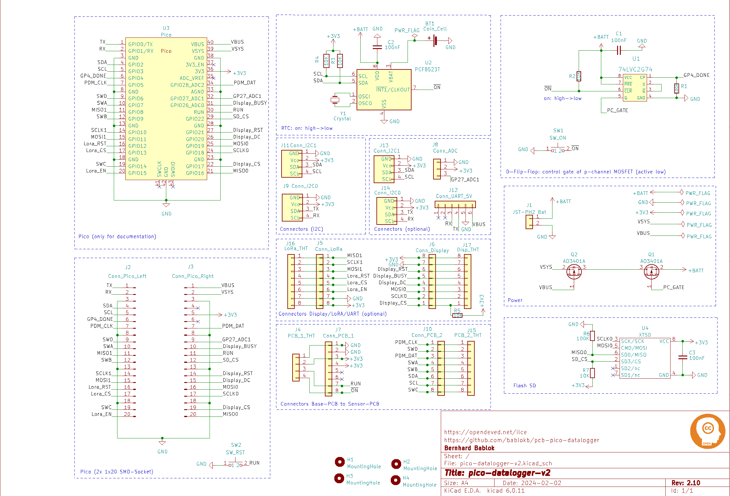
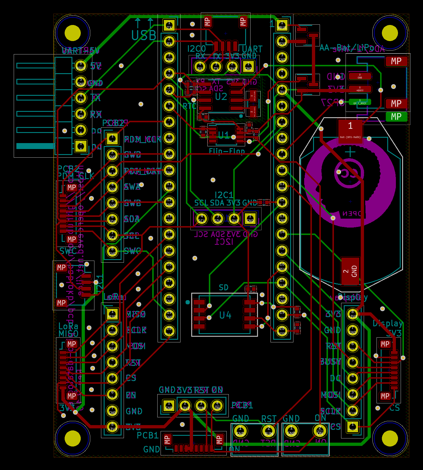
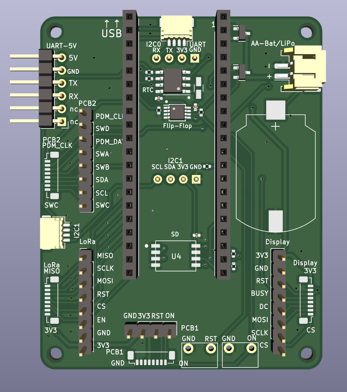
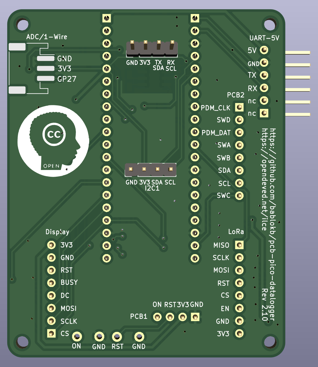
The LoRa-adapter is for the Adafruit LoRa breakouts. The LoRa-PCB is our own PCB including the RFM-chip, SURS-connector and u.FL-connector.
Wiring is independent of the base-PCB version.
LoRa adapters:
LoRa-PCBs:

This work is licensed under a Creative Commons Attribution-ShareAlike 4.0 International License.

| Qty | Value | Footprint | References |
|---|---|---|---|
| 5 | 10K | Resistor_SMD:R_0402_1005Metric | R2, R3, R4, R5, R7 |
| 4 | MountingHole | MountingHole:MountingHole_2.5mm | H1, H2, H3, H4 |
| 3 | 100nF | Capacitor_SMD:C_0402_1005Metric | C1, C2, C3 |
| 2 | 100K | Resistor_SMD:R_0402_1005Metric | R1, R6 |
| 2 | AO3401A | Package_TO_SOT_SMD:SOT-23 | Q1, Q2 |
| 1 | 74LVC2G74 | Package_SO:TSSOP-8_3x3mm_P0.65mm | U1 |
| 1 | Coin_Cell | user:CR2032_Holder | BT1 |
| 1 | Conn_ADC | Connector_JST:JST_PH_S3B-PH-SM4-TB_1x03-1MP_P2.00mm_Horizontal | J8 |
| 1 | Conn_Display | Connector_JST:JST_SUR_BM08B-SURS-TF_1x08-1MP_P0.80mm_Vertical | J6 |
| 1 | Conn_I2C0 | Connector_JST:JST_SH_SM04B-SRSS-TB_1x04-1MP_P1.00mm_Horizontal | J9 |
| 1 | Conn_I2C1 | Connector_JST:JST_SH_SM04B-SRSS-TB_1x04-1MP_P1.00mm_Horizontal | J11 |
| 1 | Conn_LoRa | Connector_JST:JST_SUR_BM08B-SURS-TF_1x08-1MP_P0.80mm_Vertical | J5 |
| 1 | Conn_PCB_1 | Connector_JST:JST_SUR_BM08B-SURS-TF_1x08-1MP_P0.80mm_Vertical | J7 |
| 1 | Conn_PCB_2 | Connector_JST:JST_SUR_BM08B-SURS-TF_1x08-1MP_P0.80mm_Vertical | J10 |
| 1 | Conn_Pico_Left | Connector_PinSocket_2.54mm:PinSocket_1x20_P2.54mm_Vertical | J2 |
| 1 | Conn_Pico_Right | Connector_PinSocket_2.54mm:PinSocket_1x20_P2.54mm_Vertical | J3 |
| 1 | Conn_UART_5V | Connector_PinHeader_2.54mm:PinHeader_1x06_P2.54mm_Horizontal | J12 |
| 1 | Crystal | Crystal:Crystal_SMD_3215-2Pin_3.2x1.5mm | Y1 |
| 1 | Disp_THT | Connector_PinHeader_2.54mm:PinHeader_1x08_P2.54mm_Vertical | J17 |
| 1 | JST-PH2 Bat | Connector_JST:JST_PH_S2B-PH-SM4-TB_1x02-1MP_P2.00mm_Horizontal | J1 |
| 1 | LOGO | LOGO | G*** |
| 1 | LoRa_THT | Connector_PinHeader_2.54mm:PinHeader_1x08_P2.54mm_Vertical | J16 |
| 1 | PCB_1_THT | Connector_PinHeader_2.54mm:PinHeader_1x04_P2.54mm_Vertical | J4 |
| 1 | PCB_2_THT | Connector_PinHeader_2.54mm:PinHeader_1x08_P2.54mm_Vertical | J15 |
| 1 | PCF8523T | Package_SO:SOIC-8_3.9x4.9mm_P1.27mm | U2 |
| 1 | SW_ON | user:SW_PUSH_1x_6mm | SW1 |
| 1 | SW_RST | user:SW_PUSH_1x_6mm | SW2 |
| 1 | THT_I2C0 | Connector_PinHeader_2.54mm:PinHeader_1x04_P2.54mm_Vertical | J14 |
| 1 | THT_I2C1 | Connector_PinHeader_2.54mm:PinHeader_1x04_P2.54mm_Vertical | J13 |
| 1 | XTSD | user:LGA8_8X6 | U4 |
bablokb/pcb-datalogger-v1
Pico board for data-logging with power-management and micro-sd storage

bablokb/pcb-pico-app-base
Generic application base PCB for the Raspberry Pi Pico(W)


bmpc/amstrad_cpc6128_romboard
A ROM Board for the Amstrad CPC 6128 capable of loading two expansion ROMs simultaneously from an SD card.


locked/picowater
cmake -DPICOBOARD=picow -DWIFISSID=" " -DWIFIPASSWORD=" " -DSERVERIP=" " -DSERVERPORT= ..

paulbruneau/ssio-check
A bench tester for the Bally/Midway MCR Sound I/O family: the 90908 Sound I/O and the 90913 / 91483 / 91657 Super Sound I/O (Z80, two AY-3-8910s, and all of the game's input ports).

mmosko/Zx50
This is the primary CPU board for the Zx50 8-slot passive backplane system. It hosts the Z80 microprocessor (running at 5 MHz to 10 MHz) and acts as the master controller for the primary bus.
It measures 56 × 70 mm and has 2 copper layers, 1.6 mm thick.
41 parts, built around the SN74HC74N, PCF8523T and AO3401A. The full list of its parts is on this page, with links to each part's symbol and footprint where PCBKit's library has them.
From the bablokb/pcb-datalogger-v2 repository on GitHub, at the commit this page was made from: the board is pico-datalogger-v2.kicad_pcb and its schematic pico-datalogger-v2.kicad_sch. PCBKit opens the board in the browser, with nothing to install.
Its repository publishes it under the CC-BY-SA-4.0 licence: you may reuse it on that licence's terms (keep the author's notice, and for a copyleft licence share your changes alike).