
2 layers82.8 × 63 mm

 azerimaker/BMS_3-5S22
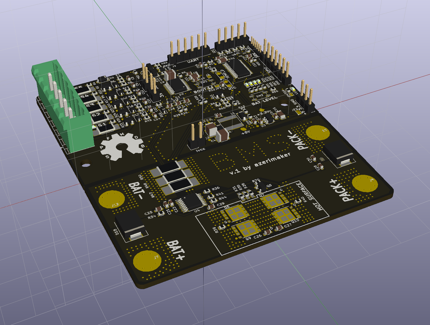
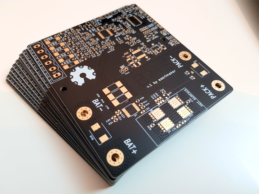
3-5S Battery Management System based on TI bq76920 IC and MSP430 uC.
Bms v1 is an open-source printed circuit board by azerimaker, from the azerimaker/BMS_3-5S repository on GitHub. It is a 2-layer board of 79 × 89 mm with 175 parts on 107 nets, routed with 2,112 tracks and 713 vias.
It is built around the MSP430G2553IPW28, LMT01LPG and MCP16301-E/CH, with the BQ76200PW, TLV70233DSE and DMN2004K among its other parts. Its parts include 69 resistors, 34 capacitors, 24 diodes, 15 connectors and 13 transistors. It belongs with the power boards and the MSP430 boards of this library.


3-5S Battery Management System based on TI bq76920 IC and MSP430 uC. The design is largely influenced by the TI's TIDA-00449 reference and LibreSolar's excellent BMS-5s designs.
| Qty | Value | Footprint | References |
|---|---|---|---|
| 22 | 1K | Resistors_SMD:R_0603 | R1, R4, R11, R14, R16, R17, R19, R20, R27, R32, R35, R38, R42, R43, R46, R51 +6 |
| 14 | 100nF | Capacitors_SMD:C_0603 | C1, C2, C6, C12, C16, C17, C18, C20, C22, C24, C28, C30, C32, C34 |
| 11 | 10K | Resistors_SMD:R_0603 | R6, R10, R12, R13, R18, R29, R37, R52, R59, R67, R68 |
| 7 | 100R | Resistors_SMD:R_0603 | R5, R25, R26, R34, R44, R54, R56 |
| 5 | 33R | Resistors_SMD:R_2010_HandSoldering | R2, R9, R15, R24, R33 |
| 5 | 5.6V | Diodes_SMD:D_SOD-323 | D5, D7, D12, D14, D17 |
| 5 | DMN2004K | TO_SOT_Packages_SMD:SOT-23 | Q1, Q2, Q3, Q4, Q8 |
| 4 | 100K | Resistors_SMD:R_0603 | R60, R61, R63, R69 |
| 4 | 3.3V | Diodes_SMD:D_SOD-323 | D9, D10, D16, D24 |
| 4 | Blue | LEDs:LED_0603 | D20, D21, D22, D23 |
| 4 | CSD18511Q5AT | Transistors:VSONP-8-1EP_5x6_Pitch1.27mm(GDS) | Q6, Q7, Q9, Q10 |
| 3 | 10uF | Capacitors_SMD:C_1210 | C3, C4, C9 |
| 3 | 1M | Resistors_SMD:R_0603 | R39, R40, R70 |
| 3 | 1uF | Capacitors_SMD:C_0603 | C8, C10, C13 |
| 3 | 2m | Resistors_SMD:R_2512_HandSoldering | R47, R48, R50 |
| 3 | 330R | Resistors_SMD:R_0603_HandSoldering | R28, R30, R31 |
| 3 | 4.7K | Resistors_SMD:R_0603 | R3, R21, R22 |
| 3 | 4.7uF | Capacitors_SMD:C_1206 | C11, C15, C31 |
| 3 | NC | Pads_Jumpers:jumper_NC | JP1, JP2, JP4 |
| 2 | 0.1uF | Capacitors_SMD:C_0603 | C26, C27 |
| 2 | 10nF | Capacitors_SMD:C_0603 | C25, C29 |
| 2 | 1N4148W-7-F | Diodes_SMD:D_SOD-123 | D1, D2 |
| 2 | 470pF | Capacitors_SMD:C_0603 | C14, C19 |
| 2 | 4R7 | Resistors_SMD:R_0603 | R36, R41 |
| 2 | SMCJ26A | Diodes_SMD:D_SMC | D18, D19 |
| 1 | 0 | Resistors_SMD:R_0603 | R53 |
| 1 | 10uF | Capacitors_SMD:C_0603 | C5 |
| 1 | 154K | Resistors_SMD:R_0603 | R62 |
| 1 | 2.2nF | Capacitors_SMD:C_0603 | C33 |
| 1 | 220nF | Capacitors_SMD:C_0603 | C21 |
| 1 | 22uH | Inductors_SMD:L_Taiyo-Yuden_NR-60xx | L1 |
| 1 | 3-4S | Pin_Headers:Pin_Header_Straight_1x02_Pitch2.54mm | J4 |
| 1 | 3.3V | Measurement_Points:Measurement_Point_Round-SMD-Pad_Small | TP2 |
| 1 | 3S | Pin_Headers:Pin_Header_Straight_1x02_Pitch2.54mm | J5 |
| 1 | 4.7nF | Capacitors_SMD:C_0603 | C7 |
| 1 | 47nF | Capacitors_SMD:C_0603 | C23 |
| 1 | 4K7 | Resistors_SMD:R_0603 | R66 |
| 1 | 500K | Resistors_SMD:R_0603 | R23 |
| 1 | 52.3K | Resistors_SMD:R_0603 | R7 |
| 1 | 5V | Measurement_Points:Measurement_Point_Round-SMD-Pad_Small | TP1 |
| 1 | BATT+ | Mounting_Holes:MountingHole_3.5mm_Pad_Via | J7 |
| 1 | BATT- | Mounting_Holes:MountingHole_3.5mm_Pad_Via | J12 |
| 1 | BOOT | Buttons_Switches_SMD:SW_SPST_EVQP2 | SW1 |
| 1 | BOOT ON/OFF | Pads_Jumpers:jumper_NO | J1 |
| 1 | BQ76200 | Housings_SSOP:TSSOP-16_4.4x5mm_Pitch0.65mm | U4 |
| 1 | BSS138 | TO_SOT_Packages_SMD:SOT-23 | Q13 |
| 1 | Balance Terminal | Connectors_Phoenix:PhoenixContact_MSTBVA-G_06x5.00mm_Vertical | J11 |
| 1 | Cell 1 | LEDs:LED_0603 | D15 |
| 1 | Cell 2 | LEDs:LED_0603 | D13 |
| 1 | Cell 3 | LEDs:LED_0603 | D8 |
| 1 | Cell 4 | LEDs:LED_0603 | D6 |
| 1 | Cell 5 | LEDs:LED_0603 | D3 |
| 1 | DB2W40300L | Diodes_SMD:D_SOD-123F | D4 |
| 1 | GPIO | Pin_Headers:Pin_Header_Straight_1x07_Pitch2.54mm | J15 |
| 1 | GREEN | LEDs:LED_0603 | D11 |
| 1 | I2C_CONN | Pin_Headers:Pin_Header_Straight_1x05_Pitch2.54mm | J14 |
| 1 | LED_Read | Buttons_Switches_SMD:SW_SPST_EVQP2 | SW2 |
| 1 | LMT01LPG | Measurement_Points:Test_Point_2Pads | U5 |
| 1 | MCP16301 | digikey-footprints:SOT-23-6 | U1 |
| 1 | MSP430G2553IPW28 | Housings_SSOP:TSSOP-28_4.4x9.7mm_Pitch0.65mm | U7 |
| 1 | Net-Tie-0R | Pads_Jumpers:Net-Tie | R49 |
| 1 | PACK+ | Mounting_Holes:MountingHole_3.5mm_Pad_Via | J8 |
| 1 | PACK- | Mounting_Holes:MountingHole_3.5mm_Pad_Via | J13 |
| 1 | RQ5A030AP | TO_SOT_Packages_SMD:SuperSOT-3 | Q11 |
| 1 | SBW | Pin_Headers:Pin_Header_Straight_1x06_Pitch1.27mm | J10 |
| 1 | SPARK_GAP | SH_Shielding_Protection:Spark_Gap_1.65x1.1 | E1 |
| 1 | TLV70233 | TO_SOT_Packages_SMD:SOT-23-5 | U3 |
| 1 | TP0610K-T1-GE3 | TO_SOT_Packages_SMD:SOT-23 | Q12 |
| 1 | TPS3839G33DBZR | digikey-footprints:SOT-23-3 | U6 |
| 1 | Thermistor | Measurement_Points:Test_Point_2Pads | J3 |
| 1 | UART | Pin_Headers:Pin_Header_Straight_1x06_Pitch2.54mm | J9 |
| 1 | VCC | Pin_Headers:Pin_Header_Straight_1x03_Pitch2.54mm | J6 |
| 1 | VCC_SELECT | Pads_Jumpers:JP_NO_NC | JP3 |
| 1 | Vcc_current | Pin_Headers:Pin_Header_Straight_1x02_Pitch2.54mm | J2 |
| 1 | ZXMP10A13F | TO_SOT_Packages_SMD:SOT-23 | Q5 |
| 1 | bq7692003PWR | Housings_SSOP:TSSOP-20_4.4x6.5mm_Pitch0.65mm | U2 |
The 172 most common of 175 parts.


Queens-Rocket-Engineering-Team/gse-control-node
The GSE control node is the control PCB for GSE systems to integrate with launch control. This includes actuator control, fan control, and a load cell reading.


wiciu15/motoHUDsch
KiCad Schematic and PCB for motoHUD (https://github.com/wiciu15/motoHUDini)


M0LTE/pi-transceiver
An attempt to build a complete ham radio transceiver around a Raspberry Pi
It measures 79 × 89 mm and has 2 copper layers, 1.6 mm thick.
175 parts, built around the MSP430G2553IPW28, LMT01LPG, MCP16301-E/CH and BQ76200PW. The full list of its parts is on this page, with links to each part's symbol and footprint where PCBKit's library has them.
From the azerimaker/BMS_3-5S repository on GitHub, at the commit this page was made from: the board is BMS_Hardware/BMS_v1/bms_v1.kicad_pcb. PCBKit opens the board in the browser, with nothing to install.
Its repository states no licence, so its author keeps all rights: ask azerimaker before reusing the design.