
4 layers81.4 × 53.2 mm
IOT development board
vinod-gunda/4_layer_IOT_Development_Board
4-layer ESP32-C3 development board designed using KiCad
89 parts

 ashfaque-ur-rahman/ESP32-Multi-Sensor-PCB
ESP32-based multi-sensor PCB with temperature/humidity, light, and microphone sensors — 4 layer Board — KiCad design based on Tech Explorations tutorial
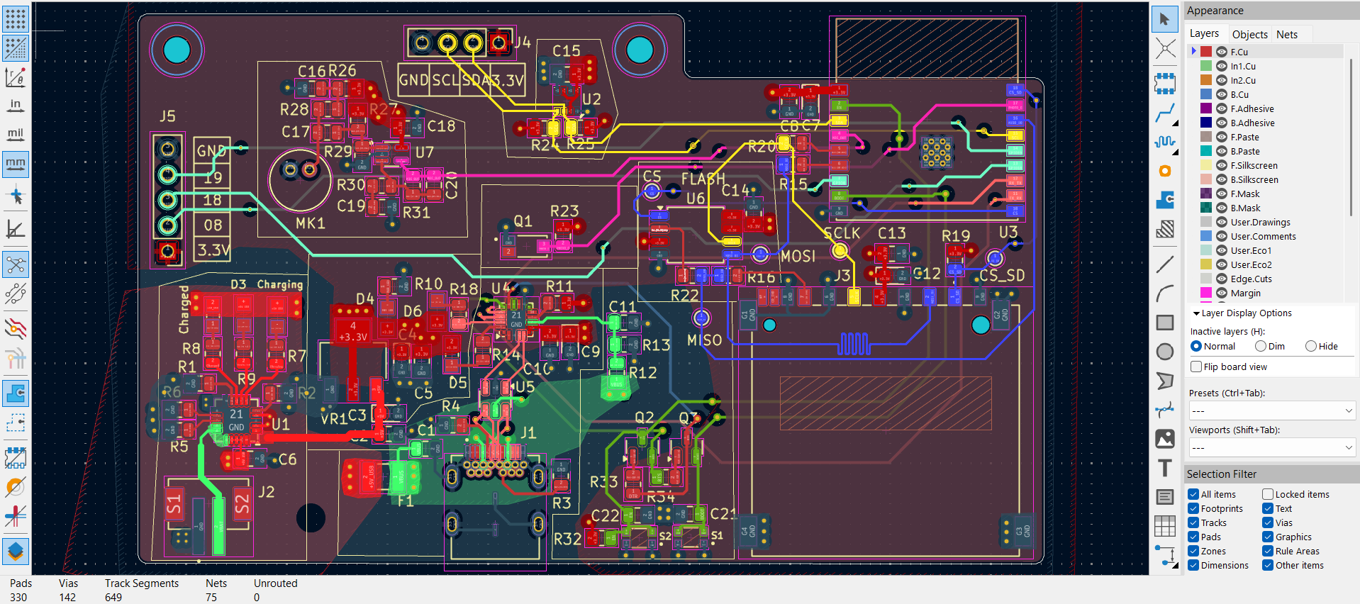
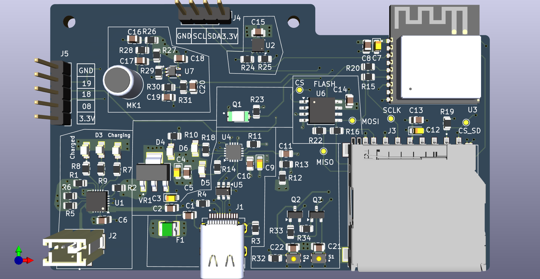
1st ESP32 Demo project is an open-source printed circuit board by ashfaque-ur-rahman, from the ashfaque-ur-rahman/ESP32-Multi-Sensor-PCB repository on GitHub. It is a 4-layer board of 90 × 54.7 mm with 87 parts on 75 nets, routed with 629 tracks and 142 vias.
It is built around the ESP32-C3-WROOM-02-H4, MCP73871EV and BME280, with the CP2102N-A02-GQFN20R, MAX4466EXK+T and W25Q32JVSSIQ among its other parts. Its parts include 32 resistors, 22 capacitors, 7 ICs, 5 connectors and 3 transistors. It belongs with the sensors and measurement and audio and music boards and the ESP32 and RISC-V boards of this library.


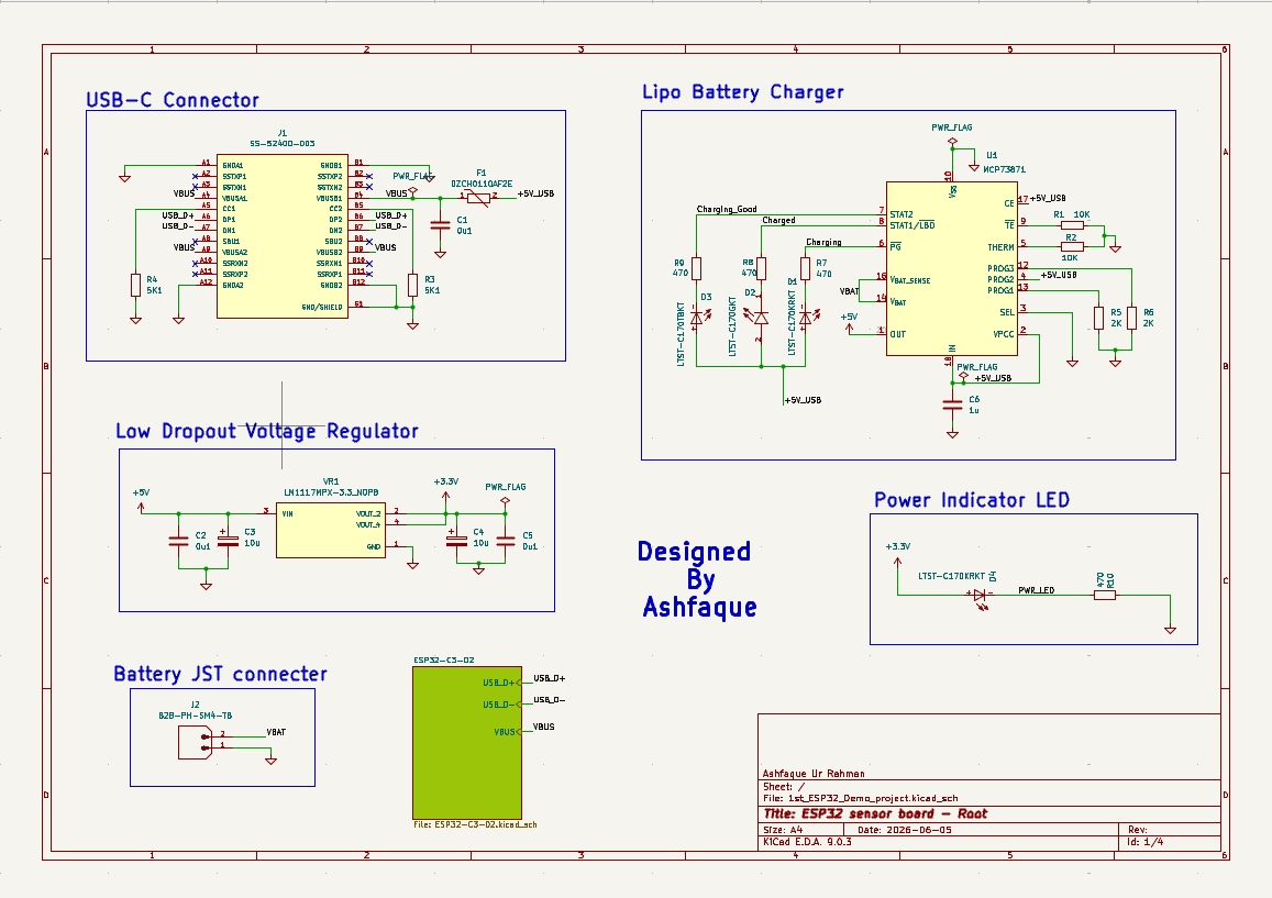
My most complex PCB design to date — an ESP32-C3 based multi-sensor IoT board featuring three sensors across a hierarchical, multi-sheet schematic. Designed over multiple days following the Tech Explorations tutorial series. This was my first experience with both 4-layer PCB stackup design and microphone amplifier circuit design.
| Property | Details |
|---|---|
| MCU | ESP32-C3 |
| Board layers | 4-layer stackup |
| Schematic structure | Hierarchical — 3 separate sheets |
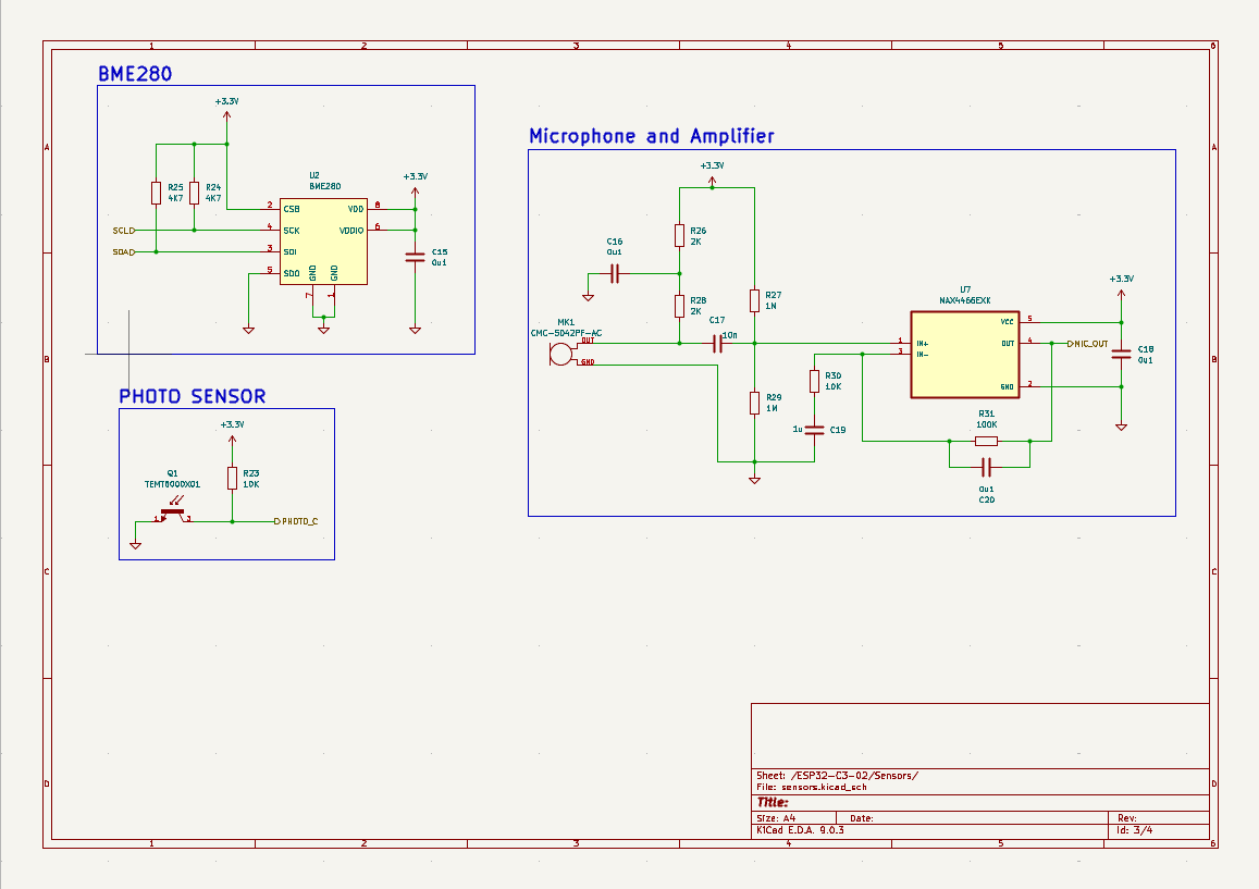
| Sensors | BME280, Electret Microphone + MAX4466EXK |
| EDA Tool | KiCad 9.0 |
| Design reference | Tech Explorations tutorial series |
| Status | Design complete |
| Layer | Function |
|---|---|
| Layer 1 (Top) | Signal + components |
| Layer 2 | Ground plane (GND) |
| Layer 3 | Power plane (VCC) |
| Layer 4 (Bottom) | Signal |
A dedicated ground plane on Layer 2 ensures low-impedance returns for all sensors and clean power distribution — critical for analog microphone signal integrity.
| Component | Part | Function | Interface |
|---|---|---|---|
| Environmental Sensor | BME280 (Bosch) | Temperature, humidity & pressure — 3-in-1 | I²C / SPI |
| Microphone | CMC-5042PF-AC (Same Sky) | 6mm omnidirectional electret condenser mic | Analog |
| Mic Amplifier | MAX4466EXK (Analog Devices) | Low-noise microphone amplifier, SC-70 package | Analog |
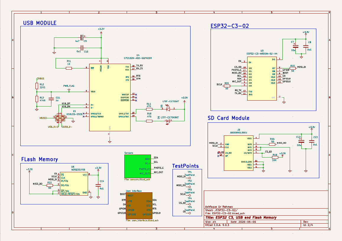
| MCU | ESP32-C3-02 | Wi-Fi + Bluetooth 5.0 LE microcontroller | — |
This design uses a hierarchical multi-sheet schematic — a professional approach for managing complex designs:
| Sheet | Contents |
|---|---|
Root page 1 | Top-level hierarchy, power distribution, ESP32-C3 core |
sensors.kicad_sch | BME280 environmental sensor + microphone + MAX4466 amplifier circuit |
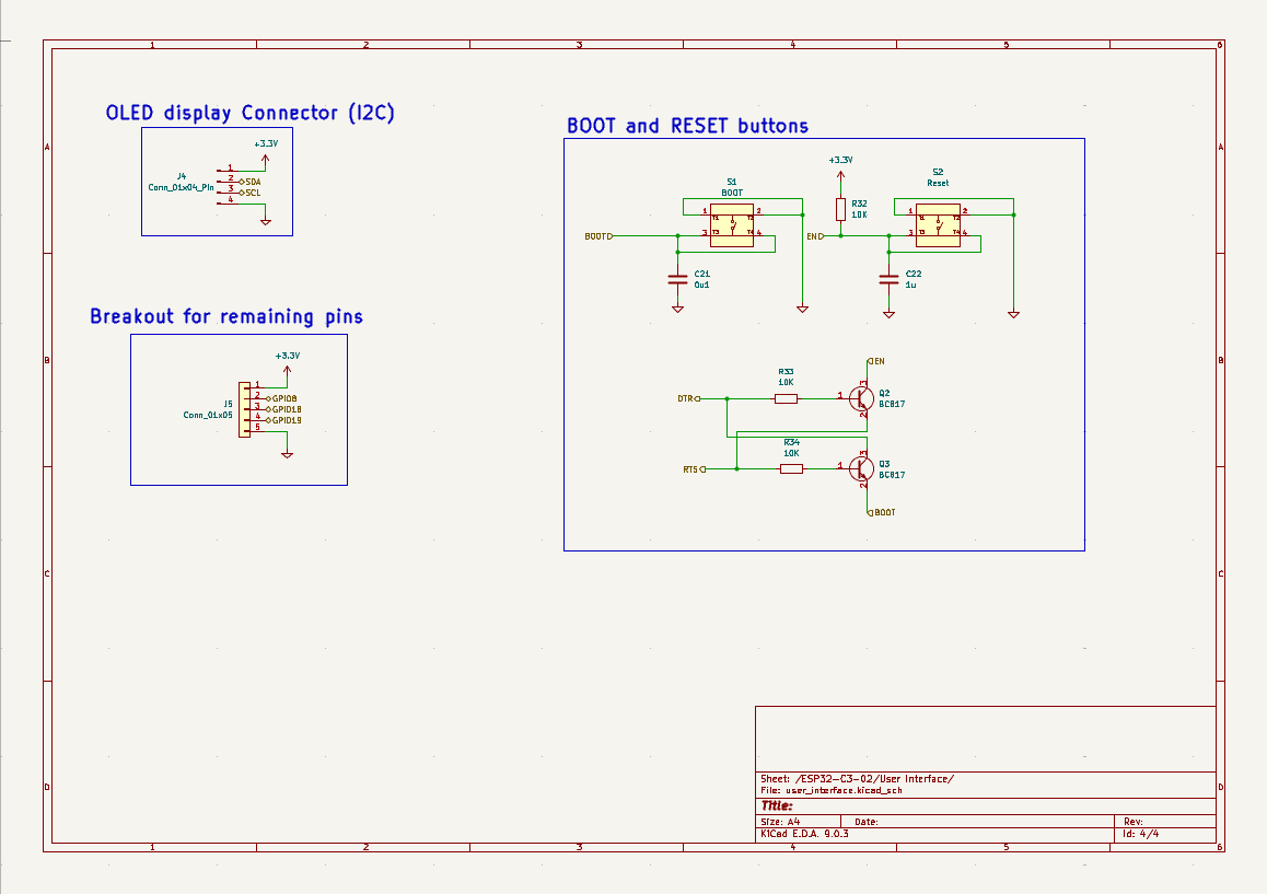
user_interface.kicad_sch | User-facing connections, GPIO breakouts, connectors |
| File | Description |
|---|---|
1st_ESP32_Demo_project.kicad_pro | KiCad project file |
1st_ESP32_Demo_project.kicad_sch | Root schematic |
ESP32-C3-02.kicad_sch | ESP32-C3 sub-schematic sheet |
sensors.kicad_sch | Sensors sub-schematic sheet |
user_interface.kicad_sch | User interface sub-schematic sheet |
1st_ESP32_Demo_project.kicad_pcb | PCB layout |
Footprints/ | Custom footprint library |

This design follows the Tech Explorations ESP32 PCB Design tutorial series.
Tech Explorations: https://www.youtube.com/@TechExplorations
Mymensingh Engineering College — EEE Department
| Qty | Value | Footprint | References |
|---|---|---|---|
| 12 | 0u1 | Capacitor_SMD:C_0805_2012Metric | C1, C2, C5, C8, C10, C13, C14, C15, C16, C18, C20, C21 |
| 8 | 10K | Resistor_SMD:R_0805_2012Metric | R1, R2, R19, R23, R30, R32, R33, R34 |
| 6 | 470 | Resistor_SMD:R_0805_2012Metric | R7, R8, R9, R10, R14, R18 |
| 5 | TestPoint | TestPoint:TestPoint_Pad_D1.0mm | CS, CS_SD, MISO, MOSI, SCLK |
| 4 | 10u | Capacitor_Tantalum_SMD:CP_EIA-2012-12_Kemet-R | C3, C4, C7, C12 |
| 4 | 1u | Capacitor_SMD:C_0805_2012Metric | C6, C11, C19, C22 |
| 4 | 2K | Resistor_SMD:R_0805_2012Metric | R5, R6, R26, R28 |
| 4 | 50 | Resistor_SMD:R_0805_2012Metric | R15, R16, R20, R22 |
| 3 | LTST-C170KRKT | LTST-C170KRKT:DIOC200X125X110 | Charging, D4, D6 |
| 2 | 1M | Resistor_SMD:R_0805_2012Metric | R27, R29 |
| 2 | 4K7 | Resistor_SMD:R_0805_2012Metric | R24, R25 |
| 2 | 5K1 | Resistor_SMD:R_0805_2012Metric | R3, R4 |
| 2 | BC817 | Package_TO_SOT_SMD:SOT-23 | Q2, Q3 |
| 2 | LTST-C170GKT | LTST-C170GKT:LED_LTST-C170GKT | Charged, D5 |
| 1 | 0ZCH0110AF2E | 0ZCH0110AF2E:FUSC3225X100N | F1 |
| 1 | 100K | Resistor_SMD:R_0805_2012Metric | R31 |
| 1 | 10n | Capacitor_SMD:C_0805_2012Metric | C17 |
| 1 | 1K | Resistor_SMD:R_0805_2012Metric | R11 |
| 1 | 22K1 | Resistor_SMD:R_0805_2012Metric | R12 |
| 1 | 47K5 | Resistor_SMD:R_0805_2012Metric | R13 |
| 1 | 4u7 | Capacitor_Tantalum_SMD:CP_EIA-2012-12_Kemet-R | C9 |
| 1 | B2B-PH-SM4-TB | B2B-PH-SM4-TB:JST_B2B-PH-SM4-TB | J2 |
| 1 | BME280 | Package_LGA:Bosch_LGA-8_2.5x2.5mm_P0.65mm_ClockwisePinNumbering | U2 |
| 1 | BOOT | USLPT2819DT2TR:SW_USLPT2819DT2TR | S1 |
| 1 | CMC-5042PF-AC | CMC-5042PF-AC:CUI_CMC-5042PF-AC | MK1 |
| 1 | CP2102N-A02-GQFN20R | Package_DFN_QFN:SiliconLabs_QFN-20-1EP_3x3mm_P0.5mm_EP1.8x1.8mm | U4 |
| 1 | Conn_01x04_Pin | Connector_PinHeader_2.54mm:PinHeader_1x04_P2.54mm_Vertical | J4 |
| 1 | Conn_01x05 | Connector_PinHeader_2.54mm:PinHeader_1x05_P2.54mm_Vertical | J5 |
| 1 | ESP32-C3-WROOM-02-H4 | ESP32-C3-WROOM-02-H4:MODULE_ESP32-C3-WROOM-02-H4 | U3 |
| 1 | GSD090012SEU | GSD090012SEU:AMPHENOL_GSD090012SEU | J3 |
| 1 | LM1117MPX-3.3_NOPB | LM1117MPX-3.3_NOPB:VREG_LM1117MPX-3.3_NOPB | VR1 |
| 1 | LTST-C170TBKT | LTST-C170KRKT:DIOC200X125X110 | D3 |
| 1 | MAX4466EXK | MAX4466EXK:SOT65P210X110-5N | U7 |
| 1 | MCP73871 | Package_DFN_QFN:QFN-20-1EP_4x4mm_P0.5mm_EP2.5x2.5mm | U1 |
| 1 | Reset | USLPT2819DT2TR:SW_USLPT2819DT2TR | S2 |
| 1 | SS-52400-003 | SS-52400-003:BELFUSE_SS-52400-003 | J1 |
| 1 | TEMT6000X01 | TEMT6000X01:TRANS_TEMT6000X01 | Q1 |
| 1 | USBLC6-2SC6 | Package_TO_SOT_SMD:SOT-23-6 | U5 |
| 1 | W25Q32JVSS | Package_SO:SOIC-8_5.3x5.3mm_P1.27mm | U6 |
The 85 most common of 87 parts.
vinod-gunda/4_layer_IOT_Development_Board
4-layer ESP32-C3 development board designed using KiCad

Raghav9git/ESP-32-IoT-PCB-Board-
A compact 4-layer IoT development board built around the ESP32-C3, integrating environmental sensing, local storage, USB-C power with LiPo battery management, and a programming/debug interface on a single board.

aryan-asit/Telemetry-iot-project
In this project , a 4 layer custom pcb is made for Telematics

EngMeesh/ESP32_IoT_Dev_Board
A custom 4-layer IoT development board based on the ESP32-C3, featuring integrated LiPo battery management, a CP2102N USB-UART bridge, MicroSD support, and onboard environmental/audio sensors for embedded engineering…

SarthakDas2006/ESP32-C3-IoT-Embedded-Custom_PCB
4-layer ESP32-C3 based custom embedded IoT PCB featuring onboard temperature & humidity, light, and audio sensing, USB Type-C, Li-Po charging, and external flash memory.

JoseSanchez122/ESP32_custom_board
Custom ESP32-WROOM-32 PCB with DHT22 (temperature/humidity), BH1750 (light), and MPU-6050 (motion) sensors, 3.3V regulator, USB-C/battery input, Wi-Fi/Bluetooth, GPIO/I2C pins, LED, and reset button, for compact IoT…

landjas09/Secure-Ready-Battery-Powered-Edge-Logger
Custom ESP32-C3 Secure-Ready Battery-Powered Edge Logger with environmental, light and acoustic sensing, local storage, DS3231 RTC, BQ27441 fuel gauging, SE050E2 secure element and TPS63802 buck-boost power.

marwantm/esp32-sensor-board
ESP32-C3 IoT sensor node with USB-C power path management — KiCad PCB design project
It measures 90 × 54.7 mm and has 4 copper layers, 1.6 mm thick.
87 parts, built around the ESP32-C3-WROOM-02-H4, MCP73871EV, BME280 and CP2102N-A02-GQFN20R. The full list of its parts is on this page, with links to each part's symbol and footprint where PCBKit's library has them.
From the ashfaque-ur-rahman/ESP32-Multi-Sensor-PCB repository on GitHub, at the commit this page was made from: the board is 1st_ESP32_Demo_project.kicad_pcb and its schematic 1st_ESP32_Demo_project.kicad_sch. PCBKit opens the board in the browser, with nothing to install.
Its repository states no licence, so its author keeps all rights: ask ashfaque-ur-rahman before reusing the design.