8 layers100 × 65 mm
MatrixDrive RevB
Matrixite/MatrixDrive
MatrixDrive is a USB-loadable Mega Drive/Genesis cartridge
143 parts

 arrow53/RoomTempHumidity
A local whole-house temperature and humidity monitor. USB-powered room sensors send measurements over Thread to a Raspberry Pi base unit, which stores history and presents a touchscreen dashboard without requiring a…
Room sensor is an open-source printed circuit board by arrow53, from the arrow53/RoomTempHumidity repository on GitHub. It is a 2-layer board of 45 × 55 mm with 24 parts on 52 nets, routed with 299 tracks and 48 vias.
It is built around the SHT40-AD1B-R3, AN54LQ-P15 and LT1761IS5-3.3#TRMPBF, with the TPD2E2U06DCKR-TP, RC0603FR-0710KL and MF-MSMF020-2 among its other parts. Its parts include 5 capacitors, 4 resistors, 4 ICs, 2 connectors and 1 diode. It belongs with the sensors and measurement boards of this library.


A local whole-house temperature and humidity monitor. USB-powered room sensors send measurements over Thread to a Raspberry Pi base unit, which stores history and presents a touchscreen dashboard without requiring a cloud service.
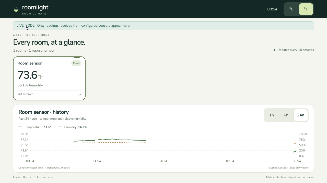
Direct capture of the running Pi display on 2026-10-11. This is the live-mode application with one reporting prototype sensor, not simulated data. Readings and freshness reflect the capture time.
flowchart LR
  S["USB room node<br/>SHT40 + nRF54L15"] -->|"Thread IPv6 / CoAP JSON"| R["nRF52840 DK<br/>RCP"]
  R -->|"Spinel / USB serial<br/>115200 RTS/CTS"| O["Pi 5<br/>OpenThread Border Router"]
  O --> C["Python collector<br/>aiocoap + SQLite"]
C -->|"Loopback HTTP"| D["Browser kiosk<br/>Touch Display 2"]| Enclosure A2 | Populated PCB A3 — angled 3D view |
|---|---|
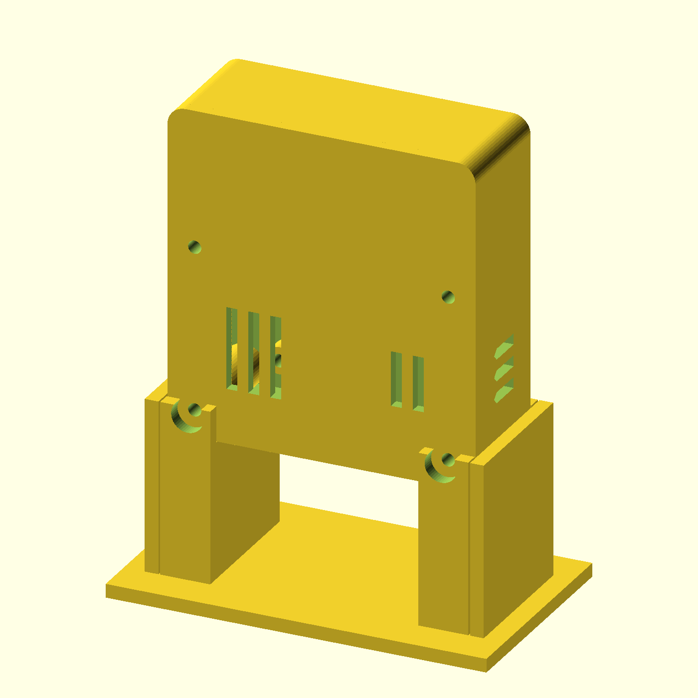 | 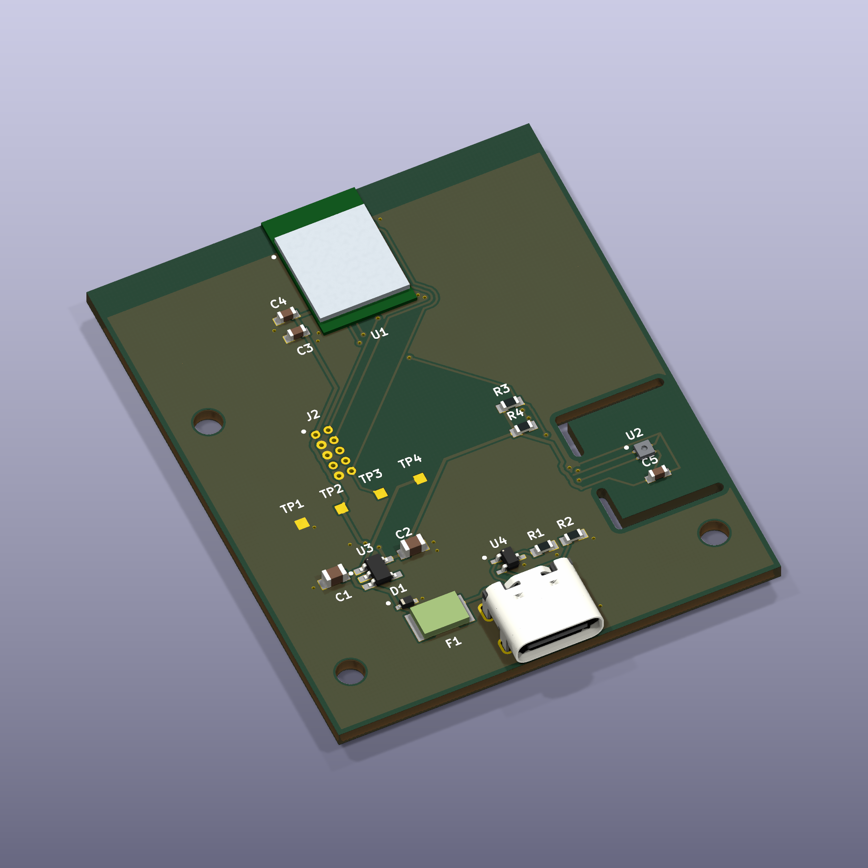 |
The enclosure is a native OpenSCAD render. The populated PCB is a native KiCad 3D render of the unchanged A3 layout and its 16 component placements. Package models show nominal geometry; the radio module uses a simplified dimension-based body/shield. Neither image proves assembled hardware qualification.
The working prototype uses an nRF54L15 DK and SHT40 breakout. The custom 45 × 55 mm PCB uses Raytac AN54LQ-P15 and SHT40; A3 changes the regulator to LT1761IS5-3.3#TRMPBF. Custom-board bring-up, printed fit, RF performance and thermal bias remain unqualified. A3 is quote/DFM only, not production/purchase approval.
| Directory | Contents |
|---|---|
| SensorFirmware | nRF54L15 DK firmware, pinned SDK manifest, schema and tests |
| SensorCase | A2 OpenSCAD, provisional print parts and fit coupons |
| SensorPCB | Current A3 native KiCad and selected quote/DFM files |
| BaseUnitFirmware | Pinned nRF52840 RCP source/build/UART reference |
| BaseUnitApplication | Pi collector/dashboard and sanitized OTBR reference |
| BaseUnitCase | Revision C digital prototype, CAD and print files; physical validation pending |
Canonical workspace: C:\GIT\RoomTempHumidity. Future tasks should read
AGENTS.md and migration notes.
Sensor firmware uses C, Nordic nRF Connect SDK v3.2.1, Zephyr and OpenThread. RCP and OTBR use separate immutable upstream commits. OTBR's documented historical build uses Debug after optimized builds failed a compiler diagnostic; warning and runtime compatibility checks were retained.
The Pi application uses Python 3.11+, aiocoap, SQLite and HTML/CSS/JavaScript. Mechanical design uses parametric OpenSCAD (sensor) and CadQuery (base case), static dimension checks and independent STL topology checks. PCB work uses native KiCad schematic/layout, project-local libraries, ERC/DRC and independent manufacturing-file audits.
Source, protocol fixtures and validation limits are preserved separately from local deployment configuration. Historical hardware success is distinguished from checks rerun on this migrated snapshot:
| Check | Publication preparation |
|---|---|
| Dashboard/collector | 26 tests passed, including loopback IPv6 CoAP, replay/storage and startup recovery |
| Sensor firmware schema | 12 tests passed |
| Enclosure static checks | 59 passed |
| Five primary STL meshes | 5 passed topology/dimension checks |
| Full target/RCP/OTBR builds | Historical success documented; not rebuilt here |
| Custom PCB / printed-case qualification | Pending |
Use the application preview, sensor build reference, RCP reference and OTBR notes. Install tools outside the repository. Real room mappings, collector addresses and commissioning credentials belong in local ignored configuration.
This is an engineering source snapshot, not a turnkey OS image or production release. Site-specific OTBR service/firewall/rollback files, full historical quotation archives and vendor 3D model bundles are omitted. See dependency limits, image provenance and licensing notice. The base-unit enclosure Revision C digital design is complete; insert, cable, slicer and physical checks remain outstanding. See its assembly and print checklist.
| Qty | Value | Footprint | References |
|---|---|---|---|
| 3 | MountingHole_2.7 | RoomNode:MountingHole_2.7 | H1, H2, H3 |
| 2 | 100nF 50V X7R | RoomNode:C_0603 | C4, C5 |
| 2 | 10k 1% | RoomNode:R_0603 | R3, R4 |
| 2 | 5.1k 1% | RoomNode:R_0603 | R1, R2 |
| 1 | +3V3 | RoomNode:TestPoint_1mm | TP2 |
| 1 | 1uF 16V X7R | RoomNode:C_0603 | C3 |
| 1 | 2.2uF 25V X7R | RoomNode:C_0805 | C1 |
| 1 | 200mA hold PTC | RoomNode:PTC_1812 | F1 |
| 1 | 4.7uF 10V X7R | RoomNode:C_0805 | C2 |
| 1 | AN54LQ-P15 | RoomNode:AN54LQ_P15_DRAFT | U1 |
| 1 | Cortex SWD 2x5 1.27 | RoomNode:SWD_2x5_1p27 | J2 |
| 1 | GND | RoomNode:TestPoint_1mm | TP1 |
| 1 | LT1761-3.3 | RoomNode:LT1761_TSOT23_5 | U3 |
| 1 | RESET_N | RoomNode:TestPoint_1mm | TP3 |
| 1 | SHT40-AD1B-R3 | RoomNode:SHT40_DFN4 | U2 |
| 1 | TPD1E10B06DYAR | RoomNode:SOD523 | D1 |
| 1 | TPD2E2U06DCKR | RoomNode:SC70_3 | U4 |
| 1 | USB4105-GF-A | RoomNode:USB4105_Custom | J1 |
| 1 | VBUS_FUSED | RoomNode:TestPoint_1mm | TP4 |
It measures 45 × 55 mm and has 2 copper layers, 1.6 mm thick.
24 parts, built around the SHT40-AD1B-R3, AN54LQ-P15, LT1761IS5-3.3#TRMPBF and TPD2E2U06DCKR-TP. The full list of its parts is on this page, with links to each part's symbol and footprint where PCBKit's library has them.
From the arrow53/RoomTempHumidity repository on GitHub, at the commit this page was made from: the board is SensorPCB/editable/room_sensor.kicad_pcb and its schematic SensorPCB/editable/room_sensor.kicad_sch. PCBKit opens the board in the browser, with nothing to install.
Its repository states no licence, so its author keeps all rights: ask arrow53 before reusing the design.
Matrixite/MatrixDrive
MatrixDrive is a USB-loadable Mega Drive/Genesis cartridge

alex1324575/snake-pcb-business-card
STM32-powered PCB business card with a 10x9 LED Snake game, USB-C power, and passive NFC. KiCad hardware, C firmware, and verification reports.

AndrewCraswell/agency
Native KiCad engineering prototype, separate from the earlier ESP32/tscircuit board. Open usb-scoring-platform.kicadpro in KiCad 10; schematic and PCB are the editable source, with no generator required.

balu-16/SeedGrant_Safety
Personal-safety project: Expo / React Native client + FastAPI + PostgreSQL (Supabase) backend + React admin portal.

adham404/Open8-VGA
An 8-bit computer from 74HC logic: microcoded CPU, VGA, PS/2, on-board editor and assembler. Play it in your browser.

mikedahlgren/Pool-Controller
This runs a pool from a Waveshare ESP32-S3-RELAY-6CH and the PoolVeras sensor hat plugged onto its Pico headers.

antmicro/oculink-pcie-adapter
PCB design which converts an OCuLink connector into x16 PCIe slot

Soulboy420/BP_flappyBird
Eigenständiger KiCad-10-Entwurf für das HAW-Bachelorprojekt. Der ursprüngliche Entwurf unter hardware/ und absichtliche Benutzerlöschungen wurden nicht überschrieben. Es wurde nichts bestellt, committed oder gepusht.