2 layers238.8 × 120.6 mm

 adham404/Open8-VGA3
An 8-bit computer from 74HC logic: microcoded CPU, VGA, PS/2, on-board editor and assembler. Play it in your browser.
Open8-vga motherboard is an open-source printed circuit board by adham404, from the adham404/Open8-VGA repository on GitHub, published under the MIT licence. It is a 6-layer board of 313 × 259.5 mm with 322 parts on 687 nets, routed with 12,299 tracks and 626 vias.
It is built around the CD74HC541E, CD74AC245E and SST39SF010A-70-4C-PHE, with the SST39SF040-70-4C-PHE, CD74HC377E and CD74HC153E among its other parts. Its parts include 138 capacitors, 135 ICs, 22 resistors, 5 connectors and 5 switches. It belongs with the computers and single-board computers and retro computing and games boards of this library.


A self-contained 8-bit computer built from 74HC/AC logic chips: a custom microcoded CPU, 32 KiB of RAM, an 80 × 30 VGA text and tile display, a PS/2 keyboard and an EEPROM for saving programs. It boots straight into a full-screen editor with a built-in assembler, so you type assembly language on the machine itself and run it, up to games like Tetris and a scrolling platformer.
Try it in your browser → The emulator runs the real boot ROM, so it is the same machine code the board would run.
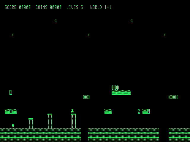
Designed by Adham Elshafei · adham_mohsen@outlook.com · 2026. Inspired by Ben Eater's 8-bit breadboard computer.
Everything is verified in simulation; no board has been built yet.
| Area | State | Docs |
|---|---|---|
| Architecture, memory map | done | 01 |
| Instruction set (102 instructions), microcode, ROM-based ALU, assembler | done, simulated | 02 |
| VGA tile controller, PS/2 receiver | done, simulated | 03 |
| Boot firmware: editor, on-board assembler, help, examples | done, simulated | 04 |
| Tetris, platformer, browser emulator | done, simulated | 05 |
| Save/load to EEPROM (4 slots) | done, simulated | 06 |
| Parts verification and timing budget against datasheets | done | 07 |
| Netlist, gate-level simulation of the whole board | done, 11 tests | 08 |
| PCB Rev A: 6 layers, routed, design-rule check clean, Gerbers | done, not fabricated | 08 |
| Parts list, assembly guide | done | 09 |
| Bring-up plan | written, not yet carried out | 10 |
| Compact-Mac-style 3D-printed case with an 8" LCD (FreeCAD) | designed, fit-checked, not printed | enclosure |
Needs only Python 3.8+ (no packages). Node.js is used by one test.
./build.shThis builds every ROM image into build/rom/, rebuilds the browser emulator
(web/open8-vga.html), regenerates the instruction-set doc, and runs the whole test suite.
web/open8-vga.html in a browser. It is one
self-contained file and needs no server.python3 tools/asm.py prog.asm -o prog.bin --listing prog.lstpython3 -m unittest discover -s testsThe Rev A board is 313 × 259.5 mm, 6 layers, all through-hole parts (hand assembly), with the nine flash chips in sockets.
| File | What |
|---|---|
hardware/fab/rev-a/open8-vga-gerbers-revA.zip | Gerbers and drill files (JLCPCB-ready) |
hardware/fab/rev-a/open8-vga-bom-revA.csv | parts list with manufacturer part numbers |
kicad/board/ | KiCad 10 project: schematic and routed board |
docs/09-assembly.md | soldering order, which ROM image goes in which socket, jumpers |
docs/10-bring-up.md | staged power-on and test plan |
The ROM images to program into the flash chips come from ./build.sh (build/rom/).
This design has not been built or tested on real hardware; treat Rev A as a first
prototype.
docs/        design notes 01-10, screenshots (02-isa.md is generated)
firmware/    boot firmware in Open8 assembly (main.asm includes the rest; gen/ is generated)
examples/    example programs, all built into the ROM (F5 in the editor)
tools/       ISA definition, ALU and microcode generators, assembler, simulators,
             VGA timing and font generators, firmware and emulator builders
             (web/open8core.js + web/page.html are the emulator sources)
web/         open8-vga.html: the built browser emulator
hardware/    design.py: the board netlist as code; gatesim.py: gate-level simulator;
             lib.py: chip models; kicad_map.py, bom.py; layout/: placement, routing and
             finishing scripts for the PCB; fab/: release fabrication files
kicad/board/ KiCad project for the PCB
enclosure/   3D-printed case: parametric FreeCAD script, STLs, renders
tests/       CPU, assembler, video, keyboard, firmware, games, EEPROM, emulator and
gate-level board testsMIT © 2026 Adham Elshafei. This covers the software, firmware, hardware design files and documentation.
| Qty | Value | Footprint | References |
|---|---|---|---|
| 134 | 100n | Capacitor_THT:C_Disc_D5.0mm_W2.5mm_P5.00mm | C1, C10, C11, C100, C101, C102, C103, C104, C105, C106, C107, C108, C109, C110, C111, C112 +118 |
| 13 | 74HC377 | Package_DIP:DIP-20_W7.62mm | U22, U30, U32, U34, U36, U37, U55, U56, U57, U78, U79, U80, U81 |
| 12 | 74HC541 | Package_DIP:DIP-20_W7.62mm | U31, U33, U35, U46, U47, U53, U54, U58, U88, U89, U101, U102 |
| 10 | 74HC153 | Package_DIP:DIP-16_W7.62mm | U28, U29, U59, U60, U61, U62, U63, U64, U65, U66 |
| 10 | 74HC163 | Package_DIP:DIP-16_W7.62mm | U21, U49, U50, U51, U52, U103, U104, U105, U106, U107 |
| 7 | 74HC32 | Package_DIP:DIP-14_W7.62mm | U13, U25, U26, U27, U69, U86, U99 |
| 6 | 10k | Resistor_THT:R_Axial_DIN0207_L6.3mm_D2.5mm_P10.16mm_Horizontal | R1, R5, R6, R11, R13, R15 |
| 6 | 74AC157 | Package_DIP:DIP-16_W7.62mm | U114, U115, U116, U120, U121, U122 |
| 6 | 74HC08 | Package_DIP:DIP-14_W7.62mm | U4, U14, U68, U72, U83, U98 |
| 6 | 74HC74 | Package_DIP:DIP-14_W7.62mm | U8, U12, U15, U84, U85, U87 |
| 5 | 74HC04 | Package_DIP:DIP-14_W7.62mm | U6, U48, U82, U96, U124 |
| 5 | 74HC161 | Package_DIP:DIP-16_W7.62mm | U42, U43, U44, U45, U94 |
| 5 | SST39SF010A | Package_DIP:DIP-32_W15.24mm_Socket | U17, U18, U19, U108, U200 |
| 4 | 1k | Resistor_THT:R_Axial_DIN0207_L6.3mm_D2.5mm_P10.16mm_Horizontal | R4, R7, R21, R22 |
| 4 | 74AC574 | Package_DIP:DIP-20_W7.62mm | U5, U109, U127, U129 |
| 4 | 74HC157 | Package_DIP:DIP-16_W7.62mm | U11, U70, U71, U74 |
| 4 | SST39SF040 | Package_DIP:DIP-32_W15.24mm_Socket | U38, U39, U40, U41 |
| 3 | 470 | Resistor_THT:R_Axial_DIN0207_L6.3mm_D2.5mm_P10.16mm_Horizontal | R12, R14, R16 |
| 3 | 47k | Resistor_THT:R_Axial_DIN0207_L6.3mm_D2.5mm_P10.16mm_Horizontal | R2, R3, R10 |
| 3 | 74HC138 | Package_DIP:DIP-16_W7.62mm | U75, U76, U77 |
| 3 | 74HC283 | Package_DIP:DIP-16_W7.62mm | U110, U111, U112 |
| 2 | 100 | Resistor_THT:R_Axial_DIN0207_L6.3mm_D2.5mm_P10.16mm_Horizontal | R17, R18 |
| 2 | 10k | Resistor_THT:R_Array_SIP9 | RN1, RN2 |
| 2 | 4.7k | Resistor_THT:R_Axial_DIN0207_L6.3mm_D2.5mm_P10.16mm_Horizontal | R8, R9 |
| 2 | 5.1k | Resistor_THT:R_Axial_DIN0207_L6.3mm_D2.5mm_P10.16mm_Horizontal | R19, R20 |
| 2 | 74AC04 | Package_DIP:DIP-14_W7.62mm | U2, U130 |
| 2 | 74AC08 | Package_DIP:DIP-14_W7.62mm | U16, U131 |
| 2 | 74AC245 | Package_DIP:DIP-20_W7.62mm | U118, U125 |
| 2 | 74HC00 | Package_DIP:DIP-14_W7.62mm | U73, U117 |
| 2 | 74HC02 | Package_DIP:DIP-14_W7.62mm | U20, U100 |
| 2 | 74HC11 | Package_DIP:DIP-14_W7.62mm | U95, U123 |
| 2 | 74HC14 | Package_DIP:DIP-14_W7.62mm | U9, U91 |
| 2 | 74HC154 | Package_DIP:DIP-24_W15.24mm | U23, U24 |
| 2 | 74HC164 | Package_DIP:DIP-14_W7.62mm | U92, U93 |
| 2 | 74HC574 | Package_DIP:DIP-20_W7.62mm | U119, U126 |
| 2 | 74HC86 | Package_DIP:DIP-14_W7.62mm | U3, U113 |
| 2 | AS6C6264 | Package_DIP:DIP-28_W15.24mm | U202, U203 |
| 1 | 10n | Capacitor_THT:C_Disc_D5.0mm_W2.5mm_P5.00mm | C4 |
| 1 | 1M | Potentiometer_THT:Potentiometer_Bourns_3386P_Vertical | RV1 |
| 1 | 1N4148 | Diode_THT:D_DO-35_SOD27_P7.62mm_Horizontal | D1 |
| 1 | 1u | Capacitor_THT:C_Disc_D5.0mm_W2.5mm_P5.00mm | C3 |
| 1 | 200mA | Fuse:Fuse_1812_4532Metric | F1 |
| 1 | 25.175MHz | Oscillator:Oscillator_DIP-14 | X1 |
| 1 | 25LC512 | Package_DIP:DIP-8_W7.62mm | U90 |
| 1 | 2A | Fuse:Fuse_1812_4532Metric | F2 |
| 1 | 2N3904 | Package_TO_SOT_THT:TO-92_Inline | Q1 |
| 1 | 470u | Capacitor_THT:CP_Radial_D10.0mm_P5.00mm | C6 |
| 1 | 47n | Capacitor_THT:C_Disc_D5.0mm_W2.5mm_P5.00mm | C5 |
| 1 | 74AC138 | Package_DIP:DIP-16_W7.62mm | U67 |
| 1 | 74AC151 | Package_DIP:DIP-16_W7.62mm | U128 |
| 1 | 74AC161 | Package_DIP:DIP-16_W7.62mm | U1 |
| 1 | 74HC05 | Package_DIP:DIP-14_W7.62mm | U97 |
| 1 | AS6C62256 | Package_DIP:DIP-28_W15.24mm | U201 |
| 1 | COL_B | Connector_PinHeader_2.54mm:PinHeader_1x02_P2.54mm_Vertical | JP5 |
| 1 | COL_G | Connector_PinHeader_2.54mm:PinHeader_1x02_P2.54mm_Vertical | JP4 |
| 1 | COL_R | Connector_PinHeader_2.54mm:PinHeader_1x02_P2.54mm_Vertical | JP3 |
| 1 | CONTINUE | Button_Switch_THT:SW_PUSH_6mm | SW5 |
| 1 | EXPANSION | Connector_PinHeader_2.54mm:PinHeader_2x20_P2.54mm_Vertical | J5 |
| 1 | HALF | Connector_PinHeader_2.54mm:PinHeader_1x02_P2.54mm_Vertical | JP1 |
| 1 | HALT | LED_THT:LED_D3.0mm | D4 |
| 1 | LOGIC | Connector_PinHeader_2.54mm:PinHeader_2x20_P2.54mm_Vertical | J4 |
| 1 | MCBANK | Connector_PinHeader_2.54mm:PinHeader_1x02_P2.54mm_Vertical | JP2 |
| 1 | MCP130-450 | Package_TO_SOT_THT:TO-92_Inline | U7 |
| 1 | NE555 | Package_DIP:DIP-8_W7.62mm | U10 |
| 1 | PS/2 | HeyPCB_LCSC:DC-IN-TH_MD-60SM | J1 |
| 1 | PWR | LED_THT:LED_D3.0mm | D3 |
| 1 | RESET | Button_Switch_THT:SW_PUSH_6mm | SW1 |
| 1 | RUN/STEP | Button_Switch_THT:SW_Slide_SPDT_Straight_CK_OS102011MS2Q | SW2 |
| 1 | SMBJ5.0A | Diode_SMD:D_SMB | D2 |
| 1 | STEP | Button_Switch_THT:SW_PUSH_6mm | SW4 |
| 1 | STEP/SLOW | Button_Switch_THT:SW_Slide_SPDT_Straight_CK_OS102011MS2Q | SW3 |
| 1 | USB-C power | Connector_USB:USB_C_Receptacle_GCT_USB4125-xx-x_6P_TopMnt_Horizontal | J3 |
| 1 | VGA | Connector_Dsub:DSUB-15-HD_Socket_Horizontal_P2.29x1.90mm_EdgePinOffset3.03mm_Housed_MountingHolesOffset4.94mm | J2 |
| 1 | piezo | Buzzer_Beeper:Buzzer_12x9.5RM7.6 | BZ1 |
It measures 313 × 259.5 mm and has 6 copper layers, 1.6 mm thick.
322 parts, built around the CD74HC541E, CD74AC245E, SST39SF010A-70-4C-PHE and SST39SF040-70-4C-PHE. The full list of its parts is on this page, with links to each part's symbol and footprint where PCBKit's library has them.
From the adham404/Open8-VGA repository on GitHub, at the commit this page was made from: the board is kicad/board/open8-vga-motherboard.kicad_pcb and its schematic kicad/board/open8-vga-motherboard.kicad_sch. PCBKit opens the board in the browser, with nothing to install.
Its repository publishes it under the MIT licence: you may reuse it on that licence's terms (keep the author's notice, and for a copyleft licence share your changes alike).


bablokb/pcb-power-connect
Feed power to the Raspberry Pi using Pins 2 and 4


EZam1992/555_Timer_Boards_PCBA
The 555 Timer Board is a beginner-friendly electronics project designed to introduce the author to the process of designing and manufacturing printed circuit boards (PCBs).


Robert-Riordan-UCD/8_Bit_CPU_PCB
PCB version of Ben Eaters 8-bit breadboard computer

kashishkebab9/omni-mapper
Omni-Wheeled Robot with custom PCB All Mechanical Assemblies, PCBs, Firmware, and Software designed, architected and programmed by Kashish Garg