4 layers65 × 45 mm
03-final E
ramtuc/rp2040-logic-analyzer
RP2040 + TXU0104 16ch logic analyzer board for PulseView (sigrok-pico), 4-layer, JLCPCB PCBA
82 partsCERN-OHL-P-2.0
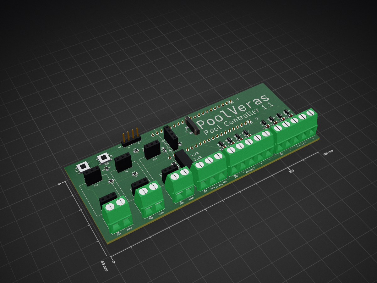
 mikedahlgren/Pool-Controller
This runs a pool from a Waveshare ESP32-S3-RELAY-6CH and the PoolVeras sensor hat plugged onto its Pico headers.
Sensor hat is an open-source printed circuit board by mikedahlgren, from the mikedahlgren/Pool-Controller repository on GitHub. It is a 2-layer board of 120 × 49 mm with 69 parts on 42 nets, routed with 209 tracks and 23 vias.
It is built around the CL21B104KCFSFNE, BAT54SLT1G and RC0805FR-0710KL, with the PPPC031LFBN-RC, PPPC201LFBN-RC and TS-1187A-B-A-B among its other parts. Its parts include 28 resistors, 16 connectors, 9 capacitors, 8 diodes and 3 switches. It belongs with the sensors and measurement boards of this library.


This runs a pool from a Waveshare ESP32-S3-RELAY-6CH and the PoolVeras sensor hat plugged onto its Pico headers.
The Waveshare board talks to the pump, switches the acid pump and the pool light, and reports its own chip temperature. The hat is where the sensors connect: Atlas probe circuits, a 4-20 mA filter-pressure sender, optional pH current loop, DS18B20 temperature sensors, and dry contacts. Home Assistant and the page at http://pool-controller.local show the readings. Once an hour the controller can post pH and water temperature to PoolVeras.
| Job | Board |
|---|---|
| Pentair IntelliFlo on RS485 | Waveshare, GPIO17 and GPIO18 |
| Acid pump | Waveshare relay CH2, GPIO2 |
| Pool light | Waveshare relay CH6, GPIO46 |
| Waterfall relay | Waveshare relay CH1, GPIO1. Leave it off unless you use it |
| Board temperature | Inside the ESP32-S3. This is the chip, not the pool |
| Atlas pH, ORP, salinity, RTD, or dissolved oxygen | Hat sockets. Any of those boards can go in any pair |
| Filter pressure and other 4-20 mA loops | Hat screw J8. Each loop needs its own 12 V or 24 V supply |
| Air and water temperature | Hat screw J6, DS18B20 sensors. SW3 selects the pull-up. Use 4.7k, handle toward the USB edge |
| Display buttons | SW1 is GPIO7 and SW2 is GPIO6. J17 is the same two switches |
| Dry contacts | Hat screw J7. A bare switch to the GND screw. ON means closed |
CH3, CH4, and CH5 on the Waveshare are free. The hat's 3.3 V rail, through fuse F1, powers the Atlas boards and the 1-Wire sensors. It does not power the 4-20 mA loops.
Screw order on the hat, left to right, is J3 through J8. Probe returns land on PGND next to PRB, not on the board ground screws.
Connector-by-connector wiring is in esphome/README.md. The Waveshare header and onboard GPIO map is in hardware/WAVESHARE_PINOUT.md. Acid dosing is in esphome/ACID_PH.md. Filter pressure is in esphome/FILTER_PRESSURE.md. The board files are in hardware/sensor-hat.
Use ESPHome 2025.9.0 or newer.
From Home Assistant, paste esphome/ha-pool-controller.yaml into ESPHome Builder. It loads the rest of the firmware from the PoolverasV1 branch. Copy the keys in esphome/secrets.yaml.example into Home Assistant's secrets.yaml, then Install.
From a clone of this repo:
esphome run esphome/pool-controller.yaml| Qty | Value | Footprint | References |
|---|---|---|---|
| 9 | 100nF | PCM_JLCPCB:C_0805 | C3, C4, C5, C6, C7, C8, C9, C10, C11 |
| 9 | 1k | PCM_JLCPCB:R_0805 | R5, R6, R7, R8, R9, R10, R11, R12, R26 |
| 8 | BAT54S | Package_TO_SOT_SMD:SOT-23 | D1, D2, D3, D4, D5, D6, D7, D8 |
| 6 | 10k | PCM_JLCPCB:R_0805 | R13, R14, R15, R16, R29, R30 |
| 6 | EZO socket, top | PinSocket_1x03_P2.54mm_Vertical | J9, J10, J11, J12, J13, J14 |
| 5 | 100 | PCM_JLCPCB:R_0805 | R17, R18, R19, R20, R21 |
| 4 | 150 | PCM_JLCPCB:R_0805 | R1, R2, R3, R4 |
| 3 | 4.7k | PCM_JLCPCB:R_0805 | R24, R27, R28 |
| 2 | 1x20 socket, bottom | PinSocket_1x20_P2.54mm_Vertical | J1, J2 |
| 2 | push | Button_Switch_SMD:SW_Push_1P1T_XKB_TS-1187A | SW1, SW2 |
| 1 | 0.2A | Fuse:Fuse_1812_4532Metric | F1 |
| 1 | 1-Wire | TerminalBlock_Phoenix_MKDS-1,5-3-5.08_1x03_P5.08mm_Horizontal | J6 |
| 1 | 2.2k | PCM_JLCPCB:R_0805 | R25 |
| 1 | 4-20 mA | TerminalBlock_Phoenix_MKDS-1,5-5-5.08_1x05_P5.08mm_Horizontal | J8 |
| 1 | EZO | SensorHat:Atlas_EZO | EZO3 |
| 1 | EZO probe | TerminalBlock_Phoenix_MKDS-1,5-2-5.08_1x02_P5.08mm_Horizontal | J5 |
| 1 | ORP | SensorHat:Atlas_EZO | EZO2 |
| 1 | ORP probe | TerminalBlock_Phoenix_MKDS-1,5-2-5.08_1x02_P5.08mm_Horizontal | J4 |
| 1 | SK13D07VG5 | SensorHat:SW_SK13D07VG5 | SW3 |
| 1 | SSD1309 | SensorHat:SSD1309 | DISP1 |
| 1 | Socket | Connector_PinSocket_2.54mm:PinSocket_1x04_P2.54mm_Vertical | J16 |
| 1 | contacts | TerminalBlock_Phoenix_MKDS-1,5-5-5.08_1x05_P5.08mm_Horizontal | J7 |
| 1 | external | Connector_PinHeader_2.54mm:PinHeader_1x04_P2.54mm_Vertical | J17 |
| 1 | pH | SensorHat:Atlas_EZO | EZO1 |
| 1 | pH probe | TerminalBlock_Phoenix_MKDS-1,5-2-5.08_1x02_P5.08mm_Horizontal | J3 |
It measures 120 × 49 mm and has 2 copper layers, 1.6 mm thick.
69 parts, built around the CL21B104KCFSFNE, BAT54SLT1G, RC0805FR-0710KL and PPPC031LFBN-RC. The full list of its parts is on this page, with links to each part's symbol and footprint where PCBKit's library has them.
From the mikedahlgren/Pool-Controller repository on GitHub, at the commit this page was made from: the board is hardware/sensor-hat/sensor-hat.kicad_pcb and its schematic hardware/sensor-hat/sensor-hat.kicad_sch. PCBKit opens the board in the browser, with nothing to install.
Its repository states no licence, so its author keeps all rights: ask mikedahlgren before reusing the design.
ramtuc/rp2040-logic-analyzer
RP2040 + TXU0104 16ch logic analyzer board for PulseView (sigrok-pico), 4-layer, JLCPCB PCBA

hkymstr/Wireless-switch
A fully wireless switch panel for a race car using two Raspberry Pi Pico 2 W boards. One board acts as the Transmitter (switch panel), the other as the Receiver (12 V output driver).


nikolajevs/PCB_EU
Сохраняются функции PCBV1: два LED-канала с общей яркостью, два независимых PWM/тахоканала вентиляторов, PTC, помпа, SHT4x, поплавок, RTC с CR2032, microSD, Wi-Fi и существующие функции интерфейса/расписаний.


adham404/Open8-VGA
An 8-bit computer from 74HC logic: microcoded CPU, VGA, PS/2, on-board editor and assembler. Play it in your browser.

scott-whitworth/bancroft_temperature_control
Supplementary material for Bancroft Experimental Temperature Control System