
2 layers112.4 × 74.2 mm

 aotta/X68KFDPi2W10
X68KFDPi2W - Floppies drive emulator All-In-One for Sharp X68000
X68KFDPI2 is an open-source printed circuit board by aotta, from the aotta/X68KFDPi2W repository on GitHub, published under the GPL-3.0 licence. It is a 2-layer board of 86.3 × 106.4 mm with 31 parts on 101 nets, routed with 868 tracks and 67 vias.
It is built around the 74LVC245AD. Its parts include 11 resistors, 9 connectors, 3 diodes, 2 ICs and 2 switches. It belongs with the RP2040 boards of this library.
X68KFDPi2W - Floppies drive emulator All-In-One for Sharp X68000
The design is an evolution of my previous X68KFDPico, and allows the two drives of the X68000 to be emulated both externally and internally connected. The engine of the emulator are two Raspberry Pico, one ‘normal’ to handle the special floppy signals and the other ‘W’ to emulate the floppies, SDcard image management and a simple web server to choose the disks to be inserted in the floppies. Ejection and insertion of the disks can be done via the two keys in the X68KFDPi2W or by connecting the cables of the original floppy keys (in case they are not present internally). The same for the internal LEDs, which are however replicated in the emulator (only the green one, the red LED is managed only for the internal one). Floppies images format supported:
| Format | Extension | Read | Write | Notes |
|---|---|---|---|---|
| Raw sector image | .HDM, .XDF | yes | yes | X68000 2HD 1232KB (77x2x8x1024); 2HC 1.2MB (80x2x15x512) also recognised by size |
| D88 | .D88, .D68, .88D | yes | yes | 2HD media, any sector layout (sector sizes, numbering, deleted data). The write protect flag of the image is honoured |
| DIM (DIFC.X) | .DIM | yes | yes | 2HD, 2HS, 2HC, 2HDE, 26x256. 2HQ (1.44MB) is not supported (needs a 300rpm drive) |
| HFE | .HFE | yes | no | the drive reports write protect |
Writing to floppy images is supported: the X68000 can copy files, format disks (FORMAT) and save games to the images on the SD card. 2D/2DD (double density) images and FM sectors are not supported.
mfm_impl.h), checks the CRC, updates the track in memory (a verify read returns the new data immediately) and saves the sectors to the SD card when the write session ends (step, side or drive change, or 100ms without writes).format: 5 sectors decoded, 3 filled with E5).WR: line per write and per save.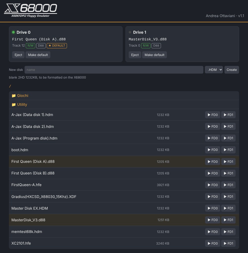
wifi.cfg; on an empty drive it makes the drive start empty at power on (★ DEFAULT tag)..HDM or .D88) in the current folder; insert it and format it on the X68000 with FORMAT.DEBUG_BUS (default 0): 1 prints MOTOR / DRIVE SELECT changes on the serial port (verbose).RESET_ON_DESELECT (default 1): the head goes back to track 0 when the drive is deselected or the motor stops. Needed by games that ask to swap disks (e.g. A-JAX).BUS_ON_INSERTED (default 0): READY and the bus outputs (74LVC245) are active only while an emulated drive is in use (motor on and drive selected), as in the 03/2025 release. With 1 they follow the disk inserted signals, and some games (e.g. Dracula) hang after loading Human68k.READY_FOLLOWS_MOTOR, DF_EN_PULLDOWN, TRK0_FOLLOWS_SELECT (default 0): experimental behaviours, off.READY_PULSE_ON_INSERT (default 1): when a disk is inserted (button), READY goes low for READY_PULSE_MS (50 ms). The FDC sees a READY change, as with a real drive; needed by games that wait for the new disk after an eject (e.g. Valis II).The second Pico handles the X68000 OPTION_SEL protocol (eject, lock, LED blink, disk in drive, interrupt). Version 1.10:
FORCE_DRIVE01 (1 = always drives 0/1, 0 = read the INTEXT jumper), DIAG (1 = print the OPTION_SEL accesses every second), EJECT_DELAY_MS, INT_REPEAT_MS, INT_GAP_US, BUTTON_MS.Valis II (original Japanese version): after the intro the game ejects disk A and waits, without any message, for the next disk (Disk D) in drive 0. Load it in drive 0 from the web page and press the insert button of drive 0.
drive.pio.h is generated from drive.pio with pioasm drive.pio drive.pio.h (the Arduino IDE does not do it).logo.h contains the web page logo (from vari/logo.png).A special thanks to Adafruit team for their great "Floppy library", from wich i starded for floppy emulation part.
NOTE Last revision fix a conflicts found when using both an internal and an external X68KFDPi2W for 4 floppy emulation, now disabled 74LVC245 when drives not enabled. Please use last PCB, X68KFDPico.u2f and X68KFDPi2W.u2f version!!
NOTE 2 Some games need tricks to properly boot, for example A-JAX works when starting with both drive off (leds off). When using 2HDboot.x for launching games from HD, you must "insert" floppy 1 & 2 pushing buttons when 2hdboot starts, then "eject" pushing again button after few seconds.


You need to add a "wifi.cfg" in root of your SDcard, with this 4 text row: SSID WIFI PASSWORD Default floppy in drive 0 Default floppy in drive 1
The 2 lines related to the default floppys can be omitted and changed everytime via Web server (a full path, e.g. /games/boot.hdm, or an empty line for an empty drive).
Gerbers file are provided for the PCB, add you pico clone, and flash the firmware ".uf2" in the Pico and in the Pico W by connecting it while pressing button on Pico and drop it in the opened windows on PC.
For any comments or questions about the projects, please use the official thread in the forum: https://nfggames.com/forum2/index.php?topic=7512.0
| Qty | Value | Footprint | References |
|---|---|---|---|
| 6 | R330 | Resistor_THT:R_Axial_DIN0207_L6.3mm_D2.5mm_P10.16mm_Horizontal | R1, R2, R3, R4, R5, R6 |
| 3 | 4.7K | Resistor_THT:R_Axial_DIN0207_L6.3mm_D2.5mm_P7.62mm_Horizontal | R9, R10, R11 |
| 2 | 10k | Resistor_THT:R_Axial_DIN0207_L6.3mm_D2.5mm_P7.62mm_Horizontal | R7, R8 |
| 2 | LED | LED_THT:LED_D3.0mm | D2, D3 |
| 2 | LOGO | logo:X68Klogo | G1, Gback |
| 2 | SW_Push | Button_Switch_THT:SW_Tactile_SPST_Angled_PTS645Vx83-2LFS | SW1, SW2 |
| 1 | 1N5817 | Diode_THT:D_DO-15_P12.70mm_Horizontal | D1 |
| 1 | 74LVC245 | Package_DIP:DIP-20_W7.62mm_Socket | U2 |
| 1 | Buzzer | Buzzer_Beeper:Buzzer_12x9.5RM7.6 | BZ1 |
| 1 | FD Ext Connector | Connector_IDC:IDC-Header_2x17_P2.54mm_Horizontal | J2 |
| 1 | FD Int/Ext (0,1/2,3) | Connector_PinHeader_2.54mm:PinHeader_1x03_P2.54mm_Vertical | J13 |
| 1 | FD00 | Connector_JST:JST_PH_B4B-PH-K_1x04_P2.00mm_Vertical | J3 |
| 1 | FD01 | Connector_JST:JST_PH_B4B-PH-K_1x04_P2.00mm_Vertical | J4 |
| 1 | FloppyPWR | Connector_PinHeader_2.54mm:PinHeader_1x04_P2.54mm_Horizontal | J9 |
| 1 | HxC Connector | Connector_IDC:IDC-Header_2x17_P2.54mm_Horizontal | J1 |
| 1 | LedFD0 | Connector_JST:JST_PH_B3B-PH-K_1x03_P2.00mm_Vertical | J7 |
| 1 | LedFD1 | Connector_JST:JST_PH_B3B-PH-K_1x03_P2.00mm_Vertical | J8 |
| 1 | Micro_SD_Card | Library:J_SD_Card-micro_socket_A | J11 |
| 1 | Pico | Library:Raspberry_Pi_PicoW_SMT_THT | U1 |
| 1 | PicoW | Library:Raspberry_Pi_PicoW_SMT_THT | RP1 |

tjboldt/Apple2-IO-RPi
Apple II expansion card using a Raspberry Pi for I/O


rallepalaveev/A2DVI
This is based on Clintech Pico Board (CPB) with 48 GPIOs, most 5V tolerant.

robfinch/Cores
Cores ===== RTF's Cores Use at your own risk. Welcome to my galaxy of cores. Contained in the directories are IP cores, source code for digital circuits.


It measures 86.3 × 106.4 mm and has 2 copper layers, 1.6 mm thick.
31 parts, built around the 74LVC245AD. The full list of its parts is on this page, with links to each part's symbol and footprint where PCBKit's library has them.
From the aotta/X68KFDPi2W repository on GitHub, at the commit this page was made from: the board is Kicad/X68KFDPI2.kicad_pcb and its schematic Kicad/X68KFDPI2.kicad_sch. PCBKit opens the board in the browser, with nothing to install.
Its repository publishes it under the GPL-3.0 licence: you may reuse it on that licence's terms (keep the author's notice, and for a copyleft licence share your changes alike).