2 layers99.6 × 69.2 mm
 TheRetroWeb/PicoPOST58
RPi Pico based POST (Power-On Self Test) Diagnostic Card
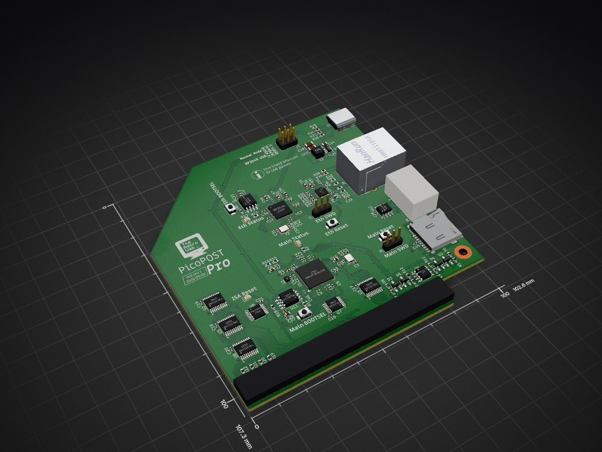
Pro rev1 is an open-source printed circuit board by TheRetroWeb, from the TheRetroWeb/PicoPOST repository on GitHub. It is a 4-layer board of 102.6 × 107.3 mm with 136 parts on 226 nets, routed with 1,575 tracks and 268 vias.
It is built around the RP2040, 74LVC245AD and W25Q32JVSSIQ, with the AP63203WU, 74LVC02APW and 24LC01B/P among its other parts. Its parts include 51 capacitors, 41 resistors, 14 ICs, 8 connectors and 7 diodes. It belongs with the RP2040 and RP2350 boards of this library.


[!NOTE] You can get a quick summary from the blog post! Introducing the PicoPOST - The Retro Web Blog
PicoPOST is a PC diagnostic card for systems with, at least, an 8-bit ISA slot. It's based around the Raspberry Pi Pico, powered by an RP2040.
PicoPOST is designed to provide many additional benefits over the basic POST cards that are commonly available from Chinese vendors on eBay and other sites.
This project is getting ready for public usage, with a few prototypes already in use for development purposes. More information soon as it gets finalized.
*: We don't have a specimen handy, so we need confirmation from someone else out there.
**: Negative voltages into a positive ADC is too much mental gymnastics without additional hardware
We are slowly compiling a YouTube playlist
with a whole bunch of demonstration pieces, showing what the PicoPOST is capable of doing.
Stay tuned for more content!
New features have been implemented with the new rev 6 PCB and matching firmware.
We make use of Visual Studio Code and the official Raspberry Pi Pico extension for an easier life. When you first open the project in VSCode, you will be prompted to install a few suggested extensions; accept the proposal and follow on-screen instructions.
You should now be greeted by the CMake and Pi Pico sidebar panels. Use the CMake panel to switch between Debug or Release builds, then refer to the Pico panel for building, uploading, and debugging the firmware.
It's already set up to probe for a compatible debugger via OpenOCD and gdbserver, and it works really well with our official Raspberry Pi Debug Probe. I expect other SWD debuggers to work just as well (J-Link, STLink, ...).
The firmware is built using the official Raspberry Pi RP2040 SDK. Follow the official documentation for setting it up.
The procedure is pretty straight-forward:
mkdir ~/repo
cd ~/repo
git clone https://github.com/TheRetroWeb/PicoPOSTcd PicoPOST
git submodule init
git submodule updateexport PICO_SDK_PATH /path/to/pico/sdk
cmake -DCMAKE_EXPORT_COMPILE_COMMANDS:BOOL=TRUE \
-DCMAKE_BUILD_TYPE:STRING=Release \
-DCMAKE_C_COMPILER:FILEPATH=/usr/bin/arm-none-eabi-gcc \
-DCMAKE_CXX_COMPILER:FILEPATH=/usr/bin/arm-none-eabi-g++ \
-S./firmware \
-B./build \
-G "Unix Makefiles"cmake --build ./build --config Release --target all -j $(nproc)There are a couple of details you might want to tune at compile time. More specifically, you may want to better calibrate the voltage monitor to show more accurate results.
In the primary firmware\CMakeLists.txt file, there are three variables you can set to skew the final ADC conversion result. These were added to account for resistor tolerances in the voltage divider circuits.
CALIBADJ_5V, correction factor for the +5V railCALIBADJ_12V, correction factor for the +12V railCalculating these factors is pretty straight forward:
Voltage Monitor modeCALIBADJ variable and build the firmware againUpdate FW menu entry. By pressing Enter, the Pico will then be rebooted into UF2 mode automatically..uf2 firmware file into the device.Info page.datasheets/ Reference documentation for components used in the PicoPOST
firmware/ Source code for the PicoPOST firmware (written in C/C++ with the official Pico SDK)
pcb/ KiCad schematics and PCB design filesThe firmware portion of PicoPOST is licensed under the MIT license.
The hardware portion of PicoPOST is licensed under the CERN OHL v2 Permissive license.
| Qty | Value | Footprint | References |
|---|---|---|---|
| 32 | 100nF | Capacitor_SMD:C_0402_1005Metric | C11, C12, C13, C14, C15, C16, C17, C18, C19, C20, C21, C23, C25, C26, C29, C36 +16 |
| 7 | 4.7uF | Capacitor_SMD:C_0603_1608Metric | C6, C10, C22, C27, C34, C46, C47 |
| 6 | 1k | Resistor_SMD:R_0603_1608Metric | R13, R14, R19, R20, R21, R22 |
| 5 | 470 | Resistor_SMD:R_0603_1608Metric | R2, R18, R27, R38, R39 |
| 4 | 10R | Resistor_SMD:R_0402_1005Metric | R29, R30, R31, R32 |
| 4 | 15pF | Capacitor_SMD:C_0402_1005Metric | C3, C5, C31, C32 |
| 4 | 47k | Resistor_SMD:R_0603_1608Metric | R6, R7, R11, R15 |
| 4 | 49.9 | Resistor_SMD:R_0603_1608Metric | R37, R40, R41, R42 |
| 4 | 74LVC245 | Package_SO:TSSOP-20_4.4x6.5mm_P0.65mm | U2, U3, U5, U8 |
| 4 | BAT54S | Package_TO_SOT_SMD:SOT-23_Handsoldering | D2, D3, D4, D5 |
| 3 | 4.7uF | Capacitor_SMD:C_0402_1005Metric | C1, C2, C4 |
| 2 | 12MHz | Crystal:Crystal_SMD_Abracon_ABM8G-4Pin_3.2x2.5mm | Y1, Y2 |
| 2 | 1K | Resistor_SMD:R_0402_1005Metric | R3, R28 |
| 2 | 200R | Resistor_SMD:R_0402_1005Metric | R4, R35 |
| 2 | 22R | Resistor_SMD:R_0603_1608Metric | R23, R24 |
| 2 | 22uF | Capacitor_SMD:C_1206_3216Metric | C28, C30 |
| 2 | 33R | Resistor_SMD:R_0402_1005Metric | R1, R34 |
| 2 | 5k1 | Resistor_SMD:R_0603_1608Metric | R25, R26 |
| 2 | 74LVC02 | Package_SO:TSSOP-14_4.4x5mm_P0.65mm | U6, U7 |
| 2 | MountingHole_Pad | MountingHole:MountingHole_3.2mm_M3_Pad | H1, H2 |
| 2 | W25Q32JVSS | Package_SO:SOIC-8_5.3x5.3mm_P1.27mm | U9, U11 |
| 1 | 1.5K | Resistor_SMD:R_0402_1005Metric | R33 |
| 1 | 100k | Resistor_SMD:R_0603_1608Metric | R9 |
| 1 | 10k | Resistor_SMD:R_0603_1608Metric | R16 |
| 1 | 10uF | Capacitor_SMD:C_0805_2012Metric | C24 |
| 1 | 12.1k | Resistor_SMD:R_0402_1005Metric | R36 |
| 1 | 12k | Resistor_SMD:R_0603_1608Metric | R8 |
| 1 | 1uF | Capacitor_SMD:C_0603_1608Metric | C33 |
| 1 | 2040 Reset | Button_Switch_SMD:SW_SPST_TS-1088-xR020 | SW4 |
| 1 | 2040 SWD | Connector_PinHeader_2.54mm:PinHeader_1x03_P2.54mm_Vertical | J7 |
| 1 | 2040 Status | LED_SMD:LED_0805_2012Metric | D9 |
| 1 | 2350 Reset | Button_Switch_SMD:SW_SPST_TS-1088-xR020 | SW3 |
| 1 | 2350 SWD | Connector_PinHeader_2.54mm:PinHeader_1x03_P2.54mm_Vertical | J6 |
| 1 | 2350 Status | LED_SMD:LED_0805_2012Metric | D1 |
| 1 | 24LC01 | Package_SO:SOIC-8_3.9x4.9mm_P1.27mm | U12 |
| 1 | 3.3uH | Inductor_SMD:L_Murata_DFE201610P | L1 |
| 1 | 3.9uH | Inductor_SMD:L_APV_ANR4030 | L2 |
| 1 | 330k | Resistor_SMD:R_0603_1608Metric | R10 |
| 1 | 39k | Resistor_SMD:R_0603_1608Metric | R5 |
| 1 | 470pF | Capacitor_SMD:C_0603_1608Metric | C35 |
| 1 | 68k | Resistor_SMD:R_0603_1608Metric | R12 |
| 1 | AP63203WU | Package_TO_SOT_SMD:TSOT-23-6 | U10 |
| 1 | FerriteBead | Inductor_SMD:L_0603_1608Metric | FB1 |
| 1 | ISA Reset | LED_SMD:LED_0805_2012Metric | D8 |
| 1 | LAN8720A | Package_DFN_QFN:VQFN-24-1EP_4x4mm_P0.5mm_EP2.5x2.5mm_ThermalVias | U14 |
| 1 | LOGO | project libraries:picopost_logo | . |
| 1 | LOGO | project libraries:postcard_stamp | . |
| 1 | LOGO | project libraries:TRW_logo | . |
| 1 | MCP6002-T/SN | Package_SO:SOIC-8_3.9x4.9mm_P1.27mm | U4 |
| 1 | MicroSD | project libraries:TF-SMD_TF-PUSH | J5 |
| 1 | P1_BS | Button_Switch_SMD:SW_SPST_TS-1088-xR020 | SW2 |
| 1 | P2_BS | Button_Switch_SMD:SW_SPST_TS-1088-xR020 | SW1 |
| 1 | PCB_Finger_ISA_8bit | IDEcardedge:BUS_IDE8 | J1 |
| 1 | RJ45_Hanrun_HR911105A_Horizontal | Connector_RJ:RJ45_Hanrun_HR911105A_Horizontal | J8 |
| 1 | RP2040 | Package_DFN_QFN:QFN-56-1EP_7x7mm_P0.4mm_EP3.2x3.2mm | U13 |
| 1 | RP2350B-QFN80 | RP2350_KiCad-main:RP2350B_QFN-80_EP_10.573x10.573_Pitch0.4mm | U1 |
| 1 | Remote SATA Connector | eec:Molex-47080-4001-0-0-0 | J4 |
| 1 | USB C | Connector_USB:USB_C_Receptacle_G-Switch_GT-USB-7010ASV | J2 |
| 1 | USB Select | Connector_PinHeader_2.54mm:PinHeader_2x03_P2.54mm_Vertical | J3 |
The 135 most common of 136 parts.


Mathesar/a500-simple-spi-hardware
Simple SPI controller for Amiga 500 with support for SD-cards and Ethernet controller


enkhbold470/ice-core
iCE40UP5K FPGA board with 8 MB PSRAM and three Pmods, programmed over USB-C by an RP2040. 6-layer KiCad 10 board.

PockyBum522/cad-pcb-projects
Various PCB projects, mostly in KiCad

ausocean/rig
Repository for AusOcean CAD files, PCB design files, 3D models and 3D modeling scripts.

Th3Link/tanklevel
This project provides a solution for measuring the liquid level in tanks, such as rainwater tanks, using the TL-136 pressure sensor.

MarkWestbroek/MusicBrain
A central brain running on teensy or a lighter MCU to process any control signals (MIDI, CV, our own) into the same but adding logic, ADSRs, DCOs, CV matrices etc. to it
It measures 102.6 × 107.3 mm and has 4 copper layers, 1.6 mm thick.
136 parts, built around the RP2040, 74LVC245AD, W25Q32JVSSIQ and AP63203WU. The full list of its parts is on this page, with links to each part's symbol and footprint where PCBKit's library has them.
From the TheRetroWeb/PicoPOST repository on GitHub, at the commit this page was made from: the board is pcb/Pro rev1/Pro rev1.kicad_pcb and its schematic pcb/ISA rev1/ISA card rev1.kicad_sch. PCBKit opens the board in the browser, with nothing to install.
Its repository states no licence, so its author keeps all rights: ask TheRetroWeb before reusing the design.