4 layers193.7 × 101.6 mm

 Mathesar/a500-simple-spi-hardware13
Simple SPI controller for Amiga 500 with support for SD-cards and Ethernet controller
A500 Simple SPI V1.3 is an open-source printed circuit board by Mathesar, from the Mathesar/a500-simple-spi-hardware repository on GitHub. It is a 2-layer board of 41.3 × 110.5 mm with 26 parts on 87 nets, routed with 667 tracks and 78 vias.
It is built around the 74LVC00AD, 74LVC02APW and 74LVC32AD, with the 74LVC74AD and 100UF/16V among its other parts. Its parts include 8 capacitors, 6 resistors, 6 ICs and 4 connectors.


Simple SPI controller for the Amiga 500 with support for SD-cards and Ethernet controller. Tested on a rev. 5 Amiga 500. It might also work on other revisions and Amiga models but that has not been tested. The design is licensed under CERN OHL-S V2.0 This repository contains the hardware CAD files. For drivers look here. This SPI controller is designed to be as simple as possible so that anyone can build it, hence the "simple" SPI controller. The design uses no programmable logic chips but only jellybean 3.3V 74LVCXX logic chips and a jellybean quad analog switch. To make it so simple compromises had to be made. The design therefore does not contain any shifting logic. This is a "bitbanging" design that can only receive or send 1 bit at a time. All the shifting is thus done by the driver software. It is not at bad as it seems though as the driver does not need to generate the SCLK signal. The SCLK signal is generated automatically by the hardware whenever a bit is read or written. Therefore, using some optimised assembly, this controller can do about 60Kbytes/sec of raw throughput on a plain Amiga 500 with no FAST ram.
It seems I often need 3 4 revisions to get things right :-).
Revision 1.0 was my first attempt. It used a 74HCT688 as the address decoder and did not set MOSI high on reads. Therefore this version had problems with SD-cards. I fixed it by using A7 instead of D7 to write but this made writes very slow. Also, the '688 is currently unobtainium. It seems that only simple logic chips like the '00 or '02 are available in all logic families.
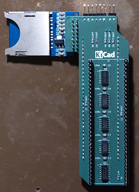
So, revision 1.1 was created that solved all above issues. This is the version you can see on the pictures. It no longer uses the 74HCT688 but a combination of OR, NOR and NAND gates. However, even 1.1 had some minor issues. Firstly I made a small mistake in the address decoder. That one was very easy to patch though and after the patch everything functions as designed. Secondly however, the PCB was slightly too large at the top left corner causing the metal shield to no longer fit. (tested on a revision 5 Amiga 500)
Therefore, revision 1.2 was created that fixes those final issues. I did not built it but it is basically revision 1.1 wwith a slightly resized PCB and the address decoder bug fixed. See here for all the files for this rev 1.2.
UPDATE 5-12-2022: The setup time on MOSI is marginal during reads. This is because of the ~DECODE signal feeding into U7A. To fix this, pin 2 of U7 should be lifted from the PCB so that it longer makes contact with the pad. This pin should then be connected to pin 3 of U7. On my system the hardware actually worked without the modification but some SD cards can get unreliable if this mod is not done
This is the latest revision incorporating the MOSI setup fix. This version has been built and verified.
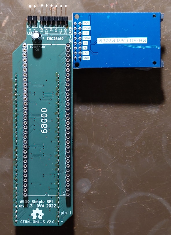
This SPI controller is intended to give an Amiga 500 an SD-card (to be used as a harddisk) and ethernet connectivity. The ethernet module is optional and connected via a pinheader and some dupont jumper cables. The SD-card module is definately not optional and soldered directly to the interface as can be seen on the pictures. The reason for this is that the SD-card module supplies 3.3V to the logic chips (and to the optional ethernet controller) via it's onboard voltage regulator. Pictures of the modules I used are in the schematic and in this repository. It is very important to use exactly the SD-card module as I used.
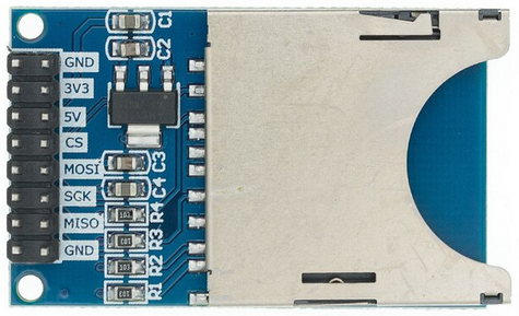
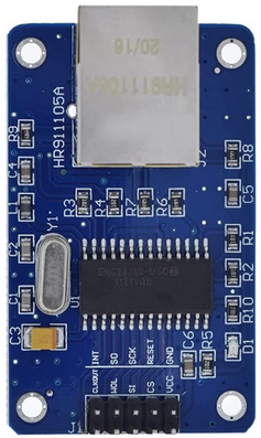
The circuit depends on the pinout and the onboard voltage regulator. The circuit also contain an old-fashioned electrolytic capacitor on the +3.3V rail. This component is also mandatory! Without it the voltage regulator on the SD-card module might become unstable. The pinheader for the SD-card actvity LED and the ethernet module should be right angle types or straight angle types bend over. Otherwise the whole setup becomes too high when the dupont cables are mounted. With right angle pins everything fits nicely under the metal shield. The pinheader that connects the controller to the 68000 socket on the A500 main board should be "turned" types with round pins. The thin part plugs into the Amiga, the thicker part is soldered on the SPI controller. This is very important as the wrong pins might damage your 68000 socket. The ethernet module does not really fit internally to the Amiga 500. I have used some long dupont cables that go through to the side expansion slot and the ethernet module is thus hanging outside. Maybe I build something like this someday.
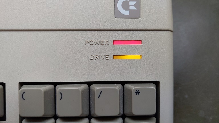
I hotglued a LED to the normal floppy LED and connected that to the LED pins on the simple SPI controller. A bit like done here except that I used a single orange LED. Hotglue is easily removed with some IPA (isopropyl alcohol) if I ever change my mind. It looks really good:
The simple SPI hardware uses a fixed address space in the upper region of the ZORRO-II IO space. Additional hardware like the A590 side-car should end up in the lower region of the ZORRO-II IO space so in theory they should not interfere. This is untested though.
A picture from the front of revision 1.1:
And a picture from the back of revision 1.1:
| Qty | Value | Footprint | References |
|---|---|---|---|
| 7 | 100n | Capacitor_SMD:C_0805_2012Metric_Pad1.18x1.45mm_HandSolder | C1, C2, C3, C6, C7, C8, C9 |
| 5 | 100E | Resistor_SMD:R_0805_2012Metric_Pad1.20x1.40mm_HandSolder | R2, R3, R4, R5, R6 |
| 1 | 100uF/16V | Capacitor_THT:C_Radial_D5.0mm_H7.0mm_P2.00mm | C5 |
| 1 | 4K7 | Resistor_SMD:R_0805_2012Metric_Pad1.20x1.40mm_HandSolder | R1 |
| 1 | 68K_Host_Interface | Package_DIP:DIP-64_W22.86mm_Socket | J1 |
| 1 | 74LVC00 | Package_SO:SOIC-14_3.9x8.7mm_P1.27mm | U3 |
| 1 | 74LVC02 | Package_SO:SOIC-14_3.9x8.7mm_P1.27mm | U7 |
| 1 | 74LVC32 | Package_SO:SOIC-14_3.9x8.7mm_P1.27mm | U5 |
| 1 | 74LVC74 | Package_SO:SOIC-14_3.9x8.7mm_P1.27mm | U6 |
| 1 | Conn_LAN_Module | Connector_PinHeader_2.54mm:PinHeader_1x06_P2.54mm_Vertical | J2 |
| 1 | Conn_SD_ACT_LED | Connector_PinHeader_2.54mm:PinHeader_1x02_P2.54mm_Vertical | J4 |
| 1 | Conn_SD_Module | Connector_PinHeader_2.54mm:PinHeader_2x08_P2.54mm_Vertical | J3 |
| 1 | DG412 | Package_SO:SOIC-16_3.9x9.9mm_P1.27mm | U2 |
| 1 | MC68000 | Package_DIP:DIP-64_W22.86mm_Socket | U1 |
The 24 most common of 26 parts.


timex-sinclair-projects/tspico-hardware
Status 2026-10-19: prototype 3 (v3.0-proto3, changes below). Proto1 (v3.0-proto1) was built and brought up; proto2 added its fixes (below).

ifilot/p2000t-teletekst-cartridge
Teletekst interfacing cartridge for the P2000T
It measures 41.3 × 110.5 mm and has 2 copper layers, 1.6 mm thick.
26 parts, built around the 74LVC00AD, 74LVC02APW, 74LVC32AD and 74LVC74AD. The full list of its parts is on this page, with links to each part's symbol and footprint where PCBKit's library has them.
From the Mathesar/a500-simple-spi-hardware repository on GitHub, at the commit this page was made from: the board is hardware/A500_Simple_SPI_V1.3.kicad_pcb and its schematic hardware/A500_Simple_SPI_V1.3.kicad_sch. PCBKit opens the board in the browser, with nothing to install.
Its repository states no licence, so its author keeps all rights: ask Mathesar before reusing the design.