10 layers120.4 × 90 mm
Bmc reference carrier board
antmicro/dc-scm-osm-l-carrier-card
DC-SCM Card supporting OSM-L System on Modules
568 parts13Apache-2.0
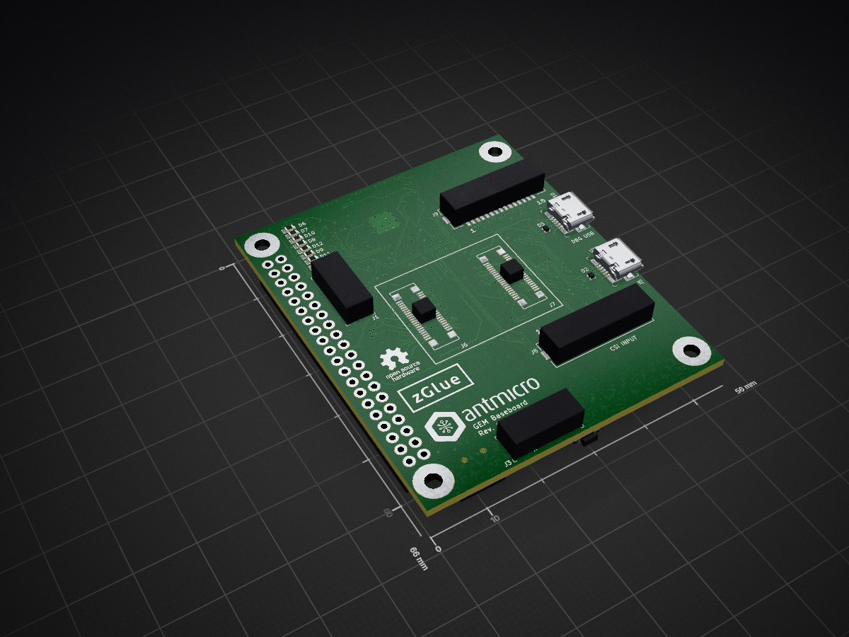
 antmicro/gem-baseboard2
This repository contains PCB design files for a demo board compatible with the GEM1 and GEM2 adapter boards.
Gem demo board is an open-source printed circuit board by antmicro, from the antmicro/gem-baseboard repository on GitHub, published under the Apache-2.0 licence. It is a 6-layer board of 56 × 66 mm with 153 parts on 213 nets, routed with 3,756 tracks and 417 vias.
It is built around the NTS0104BQ, NTB0104BQ and 93LC56CT-IMC, with the MCP1700T-3302E/TT(MS), LG L29K-G2J1-24-Z and MBR0540T1G among its other parts. Its parts include 61 resistors, 23 capacitors, 13 diodes, 10 connectors and 8 ICs.


Copyright (c) 2020 Antmicro <https://www.antmicro.com>_
.. image:: https://img.shields.io/badge/View%20on-Antmicro%20Open%20Source%20Portal-332d37?style=flat-square :target: https://opensource.antmicro.com/projects/gem-baseboard
.. figure:: img/gem-demo-board.png
This repository contains PCB design files for a demo board compatible with the GEM1 <https://github.com/antmicro/gem1-adapter>_ and GEM2 <https://github.com/antmicro/gem2-adapter>_ adapter boards.
The board acts as an evaluation carrier board for the GEM adapter boards. It includes a 4-channel FTDI USB/MPSSE converter that can be used for configuring the chiplets inside the GEM designs from an external host PC using a single USB connection and the MPSSE engine built into the FTDI controller.
The board contains two FFC connectors supporting MIPI CSI input and output. The FFC connectors are pin-compatible with the Raspberry Pi camera interface. It is possible to connect a Raspberry Pi camera module to the input connector on the board and provide processed CSI data back on the output CSI FFC. It is also possible to configure the board as an expansion hat for the Raspberry Pi platform. For more details regarding the supported connection scenarios please refer to the respective schematic sheets.
| Qty | Value | Footprint | References |
|---|---|---|---|
| 45 | R_0R_0402 | gem-demo-board-footprints:0402-res | R2, R11, R12, R13, R14, R15, R16, R17, R18, R19, R20, R21, R22, R23, R24, R25 +29 |
| 23 | TP_SMD1MM | gem-demo-board-footprints:Testpoint_smd_1mm | TP1, TP2, TP10, TP11, TP12, TP13, TP14, TP15, TP16, TP17, TP18, TP19, TP20, TP21, TP22, TP23 +7 |
| 16 | C_100n_0402_6V3 | gem-demo-board-footprints:0402-cap | C9, C10, C11, C12, C13, C14, C15, C16, C17, C18, C19, C20, C21, C22, C23, C24 |
| 8 | LG_L29K-G2J1-24-Z | gem-demo-board-footprints:LED_0603 | D6, D7, D8, D9, D10, D11, D12, D13 |
| 7 | R_330R_0402 | gem-demo-board-footprints:0402-res | R35, R36, R37, R38, R39, R40, R41 |
| 5 | C_1u_0603 | gem-demo-board-footprints:0603-cap | C1, C2, C3, C4, C5 |
| 3 | Jumper_3_Open | Jumper:SolderJumper-3_P1.3mm_Open_Pad1.0x1.5mm | VCCIO1, VCCIO2, VCCIO3 |
| 3 | MBR0540T1G | gem-demo-board-footprints:SOD-123 | D1, D3, D4 |
| 3 | NTS0104BQ | gem-demo-board-footprints:QDHVQFN14 | U2, U3, U4 |
| 3 | R_10k_0402 | gem-demo-board-footprints:0402-res | R4, R6, R7 |
| 2 | 0473460001 | gem-demo-board-footprints:USB_Micro_B_Female_0473460001 | J5, J10 |
| 2 | 3220-10-0100-00 | gem-demo-board-footprints:PinHeader_2x5_P1.27mm_Drill.7mm | J1, J3 |
| 2 | 556500488 | gem-demo-board-footprints:556500488 | J6, J7 |
| 2 | BLM18AG601SN1D | gem-demo-board-footprints:0603-res | FB1, FB2 |
| 2 | C_4u7_0402 | gem-demo-board-footprints:0402-cap | C25, C26 |
| 2 | NTB0104BQ | gem-demo-board-footprints:QDHVQFN14 | U7, U8 |
| 2 | R_2k_0402 | gem-demo-board-footprints:0402-res | R5, R10 |
| 2 | TPD2EUSB30DRTR | gem-demo-board-footprints:SOT-3 | D2, D5 |
| 2 | WE_686115148922_FLIPPED | gem-demo-board-footprints:WE_686115148922_FLIPPED | J8, J9 |
| 1 | 2x20_Header_Female | gem-demo-board-footprints:PinHeader_2x40_P2.54_Drill1mm | J4 |
| 1 | 93LC56CT-IMC | gem-demo-board-footprints:DFN-8_2x3mm | U5 |
| 1 | ASFLMB-12.000MHZ-LC-T | gem-demo-board-footprints:ASFLMB | Y1 |
| 1 | DF13A-2P-1.25H | gem-demo-board-footprints:DF13A-2P-1.25H | J2 |
| 1 | EVQPUA02K | gem-demo-board-footprints:Panasonic_EVQPUJ_EVQPUA | S1 |
| 1 | FT4232HQ | gem-demo-board-footprints:FT4232HQ | U6 |
| 1 | MCP1700T-3302E_TT | gem-demo-board-footprints:SOT-23-3 | U1 |
| 1 | R_0R_0603 | gem-demo-board-footprints:0603-res | R1 |
| 1 | R_12k_0402 | gem-demo-board-footprints:0402-res | R9 |
| 1 | R_220R_0402 | gem-demo-board-footprints:0402-res | R61 |
| 1 | R_470R_0402 | gem-demo-board-footprints:0402-res | R34 |
| 1 | antmicro_logo | gem-demo-board-footprints:antmicro-logo_scaled_20mm | N1 |
| 1 | oshw_logo | gem-demo-board-footprints:oshw-logo | N3 |
| 1 | zglue_logo | gem-demo-board-footprints:zglue-logo | N2 |
| 1 | zglue_logo_500mil | gem-demo-board-footprints:zglue-logo-10000dpi | N2 |
The 149 most common of 153 parts.
It measures 56 × 66 mm and has 6 copper layers, 1.6 mm thick.
153 parts, built around the NTS0104BQ, NTB0104BQ, 93LC56CT-IMC and MCP1700T-3302E/TT(MS). The full list of its parts is on this page, with links to each part's symbol and footprint where PCBKit's library has them.
From the antmicro/gem-baseboard repository on GitHub, at the commit this page was made from: the board is gem-demo-board.kicad_pcb. PCBKit opens the board in the browser, with nothing to install.
Its repository publishes it under the Apache-2.0 licence: you may reuse it on that licence's terms (keep the author's notice, and for a copyleft licence share your changes alike).
antmicro/dc-scm-osm-l-carrier-card
DC-SCM Card supporting OSM-L System on Modules

QuickLogic-Corp/quick-feather-dev-board
100% open source dev kit for EOS S3 MCU+eFPGA SoC supported by fully open source SDK and FPGA Toolchain

antmicro/m2-smart-iot-module
https://antmicro.com/blog/2021/08/open-hardware-smart-m2-radio-module-for-iot/

antmicro/ecp5-dc-scm
Experimental Lattice ECP5-driven Data Center Security Communication Module

antmicro/ict-baseboard
PCB design for implementing In-Circuit Testing of other PCBs via an USB-enabled host

GMUCERG/fobos
Flexible Open-source workBench fOr Side-channel analysis (FOBOS)

antmicro/arty-expansion-board
IO expansion board compatible with Digilent Arty A7
