4 layers42 × 42 mm
 andrew153d/AxisDriver1
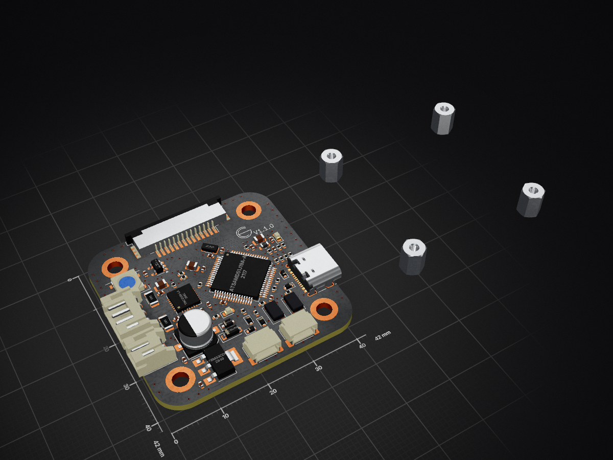
Axis Basic is an open-source printed circuit board by andrew153d, from the andrew153d/AxisDriver repository on GitHub. It is a 4-layer board of 42 × 42 mm with 76 parts on 81 nets, routed with 517 tracks and 147 vias.
It is built around the ATSAMD51J19A-AUT-EFP, AT24MAC402-XHM and TMC2209-LA, with the UA78M33CDCYR, ESD5Z3V3 and XZMDK54W-1 among its other parts. Its parts include 21 capacitors, 21 resistors, 10 diodes, 6 connectors and 5 ICs. It belongs with the SAM D and SAM boards of this library.


The AxisDriver project is a comprehensive solution for controlling motorized devices, designed for robotics and automation applications. It integrates firmware, software, and hardware components to provide a robust and flexible platform for motor control and peripheral management.
firmware/: Firmware source code, libraries, and PlatformIO configuration.examples/Python/: Python scripts for hardware interfacing and control.hardware/: KiCad files for PCB designs, including Ethernet HATs and mainboards.test/: Unit tests for hardware components.scripts/: Utility scripts for generating interfaces and managing configurations.firmware/ directory.platformio runexamples/Python/ directory.python3 <script_name>.pync -u -lk 35461| Qty | Value | Footprint | References |
|---|---|---|---|
| 10 | 10k | Resistor_SMD:R_0402_1005Metric | R5, R6, R7, R8, R9, R10, R11, R12, R14, R17 |
| 5 | 100n | Capacitor_SMD:C_0402_1005Metric | C12, C15, C16, C17, C19 |
| 5 | 1uf | Capacitor_SMD:C_0402_1005Metric | C6, C8, C9, C10, C11 |
| 5 | ESD5Z3V3 | Diode_SMD:D_SOD-523 | D3, D4, D5, D7, D8 |
| 5 | TestPoint | TestPoint:TestPoint_Pad_D2.0mm | 3.3V1, CLK1, GND1, RST1, SIO1 |
| 4 | MountingHole | MountingHole:MountingHole_3.2mm_M3_ISO14580_Pad | H1, H2, H3, H4 |
| 3 | 1k | Resistor_SMD:R_0402_1005Metric | R15, R18, R19 |
| 2 | 100k | Resistor_SMD:R_0402_1005Metric | R4, R16 |
| 2 | 10uf | Capacitor_SMD:C_0805_2012Metric | C5, C7 |
| 2 | 120m | Resistor_SMD:R_1206_3216Metric | R20, R21 |
| 2 | 22pF | Capacitor_SMD:C_0402_1005Metric | C2, C3 |
| 2 | 22u | Capacitor_SMD:C_0805_2012Metric | C18, C20 |
| 2 | 5.1k | Resistor_SMD:R_0402_1005Metric | R2, R3 |
| 2 | JST_SH | Connector_JST:JST_SH_SM04B-SRSS-TB_1x04-1MP_P1.00mm_Horizontal | J3, J4 |
| 2 | RKB2SJK | Push_Button:button_RKB2SJK250SMTR LFS | SW1, SW2 |
| 2 | XZMDK54W-1 | LED_SMD:LED_0603_1608Metric | D6, D9 |
| 1 | 0.1u | Capacitor_SMD:C_0402_1005Metric | C4 |
| 1 | 1-84952-4 | Connector_FFC-FPC:TE_1-84952-4_1x14-1MP_P1.0mm_Horizontal | J6 |
| 1 | 100 | Resistor_SMD:R_0402_1005Metric | R13 |
| 1 | 10uh | Inductor_SMD:L_0603_1608Metric | L1 |
| 1 | 1M | Resistor_SMD:R_0402_1005Metric | R1 |
| 1 | 1u | Capacitor_SMD:C_0402_1005Metric | C1 |
| 1 | 2.2u | Capacitor_SMD:C_0402_1005Metric | C14 |
| 1 | 22n | Capacitor_SMD:C_0402_1005Metric | C13 |
| 1 | 32.768 | Crystal:Crystal_SMD_3215-2Pin_3.2x1.5mm | Y1 |
| 1 | 47u | Capacitor_SMD:CP_Elec_6.3x5.4 | C21 |
| 1 | AT24MAC402 | Package_TO_SOT_SMD:SOT-23-5 | U5 |
| 1 | ATSAMD51J19A-AUT | Package_QFP:TQFP-64_10x10mm_P0.5mm | U3 |
| 1 | JST_PH | Connector_JST:JST_PH_S4B-PH-K_1x04_P2.00mm_Horizontal | J2 |
| 1 | MMSZ5254B | Diode_SMD:D_SOD-123 | D2 |
| 1 | PMEG3020EJ | Diode_SMD:D_SOD-323F | D1 |
| 1 | S2B-PH-K-S | Connector_JST:JST_PH_S2B-PH-K_1x02_P2.00mm_Horizontal | J5 |
| 1 | TLV493D | Package_TO_SOT_SMD:SOT-23-6 | U1 |
| 1 | TMC2209-LA | Package_DFN_QFN:QFN-28-1EP_5x5mm_P0.5mm_EP3.35x3.35mm_ThermalVias | U4 |
| 1 | UA78M33CDCYR | Package_TO_SOT_SMD:SOT-223-3_TabPin2 | U2 |
| 1 | USB4105-GF-A | Connector_USB:USB_C_Receptacle_GCT_USB4105-xx-A_16P_TopMnt_Horizontal | J1 |
| 1 | WS2812B | LED_SMD:LED_WS2812B_PLCC4_5.0x5.0mm_P3.2mm | D10 |
It measures 42 × 42 mm and has 4 copper layers, 1.6 mm thick.
76 parts, built around the ATSAMD51J19A-AUT-EFP, AT24MAC402-XHM, TMC2209-LA and UA78M33CDCYR. The full list of its parts is on this page, with links to each part's symbol and footprint where PCBKit's library has them.
From the andrew153d/AxisDriver repository on GitHub, at the commit this page was made from: the board is hardware/Main Board/Axis_Basic.kicad_pcb and its schematic hardware/Ethernet HAT/Ethernet HAT.kicad_sch. PCBKit opens the board in the browser, with nothing to install.
Its repository states no licence, so its author keeps all rights: ask andrew153d before reusing the design.

Twisted-Fields/rp2040-motor-controller
A dual channel brushless motor controller based on the RP2040 microcontroller, designed in Kicad.

udu3324/stepper-synth
An electronic instrument that uses stepper motors to make music


KrHaaland/GNSS_Alarm_Clock
GNSS-synchronized alarm clock — custom SAMD51J20A board with nPM1300 Li-ion power (USB-C), offline timezone+DST from coordinates, LVGL 9 on a 428x142 TFT, WAV alarm tunes over USB, battery-backed RTC

ZigEmbeddedGroup/sycl-badge
The badge for the SYCL conference! https://zigembeddedgroup.github.io/sycl-badge/

gpgreen/ahrs-can-adapter
Kicad design for Pixhawk 4 flight board to CAN network adapter


Prosthetics-Exoskeleton/Grip_Exo_PCB_V1
KiCAD design files for first iteration of grip exoskeleton PCB. Contains 10 sensor ports and space for 5 sets of solenoid valves