
2 layers172 × 152.9 mm
 AndersBNielsen/PhaseLatchMini72
High-rate continuous streaming of interleaved dual ADC (I/Q) samples over USB Full‑Speed (FS) using only the built‑in CDC class on an STM32F103C8 ("Blue Pill" style) board. Companion Python host tools provide live visualization, FIFO bridging, raw capture, diagnostics, and throughput benchmarking.
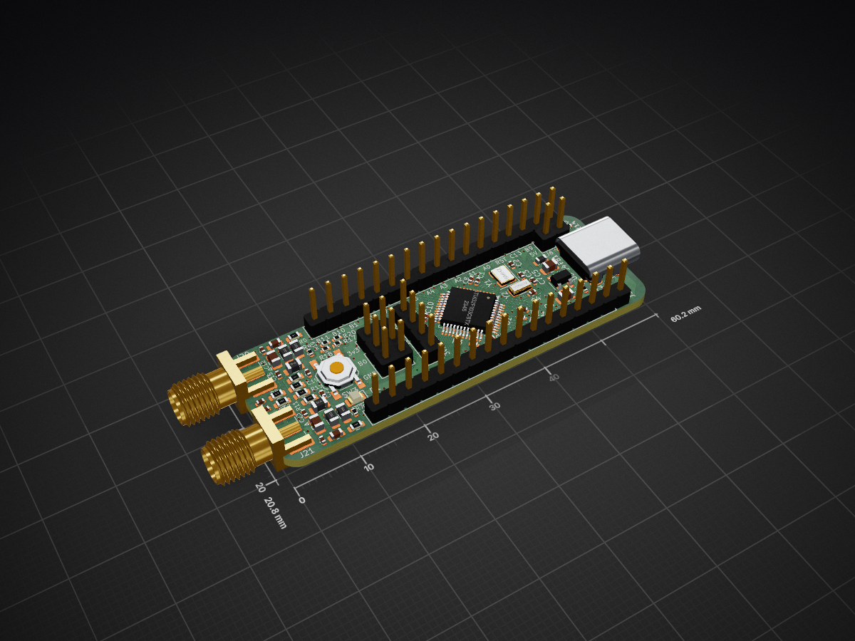
PhaseLatchMini is an open-source printed circuit board by AndersBNielsen, from the AndersBNielsen/PhaseLatchMini repository on GitHub. It is a 4-layer board of 60.2 × 20.8 mm with 63 parts on 67 nets, routed with 515 tracks and 91 vias.
It is built around the MIC5504-3.3YM5. Its parts include 23 capacitors, 19 resistors, 8 connectors, 6 inductors and 2 ICs. It belongs with the radio and wireless boards and the STM32 boards of this library.
Combined hardware + firmware + host tooling for a compact dual‑ADC I/Q capture platform.
High-rate continuous streaming of interleaved dual ADC (I/Q) samples over USB Full‑Speed (FS) using only the built‑in CDC class on an STM32F103C8 ("Blue Pill" style) board. Companion Python host tools provide live visualization, FIFO bridging, raw capture, diagnostics, and throughput benchmarking.
Status: Actively optimized. Current configured complex sample rate target: 210.5 k I/Q samples/sec (
IQ_SAMPLE_RATE_HZ= 210526) with sustained USB payload throughput >500 KiB/s. Timer PSC/ARR are selected at runtime by a search routine for the closest achievable rate; observed effective rate can be within a small delta of the target. ADC sampling time was reduced (nowADC_SAMPLETIME_28CYCLES_5) to reach this rate while maintaining conversion stability.
Origin / Intended Use: Initially developed as a lightweight streaming engine for the PhaseLoom project, but fully usable with any dual (I/Q) analog front end producing baseband signals on two STM32F1 ADC channels. Note: Phaseloom should be modified for best performance. Replace 22kOhm feedback caps with matched 47kOhm resistors and replace the output stage 50 ohms with 0 ohm.
https://www.youtube.com/watch?v=UEAtSE1PV44
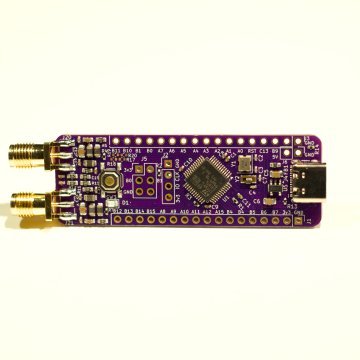
A 4‑layer purple PCB (Blue Pill footprint inspired) integrating two SMA input ports and on‑board ~100 kHz low‑pass filtering (~210 kHz complex baseband bandwidth). Designed around the STM32F103C8 in dual regular simultaneous ADC mode (ADC1 + ADC2) to stream interleaved I/Q samples over USB Full-Speed.
Quiet_Unused_Pins in main.c)All fabrication outputs live in hardware/PhaseLatchMini/production:
PhaseLatchMini.zip – Gerber/drill bundle ready for PCB fabbom.csv – Bill of Materials (with LCSC part numbers for quick JLCPCB sourcing)designators.csv – Component reference listpositions.csv – Pick‑and‑place XY + rotation for SMT assemblynetlist.ipc – IPC netlist exportDirect link (relative): hardware/PhaseLatchMini/production/PhaseLatchMini.zip
Representative components (from bom.csv):
Current passive network targets ~100 kHz corner. For alternative bandwidths:
IQ_SAMPLE_RATE_HZ (currently 210526) with dynamic TIM3 prescaler/period search (see timer_trigger_init() in iq_adc.c)ADC_SAMPLETIME_28CYCLES_5 for higher throughput (previous higher value limited rate)Inc/iq_adc.h and set #define IQ_SAMPLE_RATE_HZ <desired_rate> (I/Q pairs per second).ADC_SAMPLETIME_x) further, but watch noise/performance.FEED command) for increased busy skips.iq_dma_half_count + iq_dma_full_count over a timed host interval.A command periodically; note increments of half/full counts.host_test.py and compute rows * rate.platformio.ini # Build environments & macro flags
src/ # Firmware sources (USB, ADC, main logic)
Inc/ / include/ # Public headers
host_*.py # Python host utilities
lib/ test/ # (Placeholders / future use)Key firmware files:
src/main.c – System init, main loop USB feeder (fallback scheduling & instrumentation)src/iq_adc.c / Inc/iq_adc.h – ADC+DMA+Timer configuration, DMA IRQ scheduling kicksrc/usbd_conf.c – Low-level USB callbacks, DataIn burst chaining logicsrc/usbd_cdc_if.c – CDC interface, command parser (A/F/STATS) & data write APIsrc/usbd_raw.c (future / optional) – Raw class scaffolding (if transitioning from CDC for additional margin)Host scripts (root directory):
host_diagnostics.py – Passive capture, STATS delta decode, periodic monitor, USB descriptor infohost_throughput.py – PyUSB bulk endpoint benchmark (raw vendor class / future); shows packet statshost_raw_capture.py – Robust raw USB (PyUSB or CDC) capture with quiet mode & BrokenPipe safetyhost_iq_fifo.py – Serial CDC → named FIFO adapter (u8 or cf32) for GQRX / GNU Radiohost_iq_live.py – Terminal live IQ stats + sparklines / averageshost_test.py – Simple START/STOP based capture, optional float32 output & basic statshost_probe.py – (Currently empty placeholder for future probing utilities)Prerequisites:
pio CLI)Clone & open project, then build one of the defined environments:
If you're new to PlatformIO, these are the minimal steps to get a firmware onto the board.
platformio.ini resides).adc).Install PlatformIO Core (Python 3.11+ recommended):
pip install --upgrade platformioFrom the project root:
# List environments defined in platformio.ini
pio run --list-targets

# Build the adc environment
pio run -e adc

# Upload (adjust -e if choosing another env)
pio run -e adc -t upload

# Open a serial monitor (Ctrl+C to exit)
pio device monitor -b 115200
If you see permission errors on macOS/Linux, you may need to adjust USB device permissions or add your user to the appropriate group (e.g. dialout on some Linux distros).
On macOS you'll typically see /dev/tty.usbmodem*. On Linux, it may appear as /dev/ttyACM0. Use pio device list to enumerate.
Environments (see platformio.ini):
env:baseline – Minimal USB baseline with reduced diagnostics (throughput focus pattern)env:diag – Heavier diagnostics enabled (ASCII stat chatter)env:adc – Active dual-ADC streaming (ENABLE_IQ + throughput suppressions)env:adc_smoke – Lower-intensity validation (extra ADC status prints)Typical flow (using env:adc):
adc environment in PlatformIOpython host_test.py --progress)If enumeration stalls: power cycle board or press reset. Heartbeat LED indicates main loop alive; rapid fallback pattern indicates SysTick/USB early issues.
Send as ASCII (line ending flexible, CR/LF accepted):
START – Begin IQ streaming (if not already running)STOP – Halt streaming (host_test.py sends on exit)A – Print ADCSTAT line with ADC & DMA countersF – Print FEED line (USB feeder instrumentation)STATS – Legacy status snapshot (may be suppressed in throughput builds)Each IQ sample pair is one 32-bit little-endian word composed of two 16‑bit containers produced by the STM32F1 dual regular simultaneous ADC mode:
Bits  0..11  : I (ADC1 12-bit result, right-aligned)
Bits 12..15  : Unused (always 0)  <-- upper 4 bits of lower 16-bit half-word
Bits 16..27  : Q (ADC2 12-bit result, right-aligned)
Bits 28..31  : Unused (always 0)  <-- upper 4 bits of upper 16-bit half-word
So effectively:
uint16_t I_lane = word & 0xFFFF;          // lower half-word
uint16_t Q_lane = (word >> 16) & 0xFFFF;  // upper half-word
uint16_t I_raw12 = I_lane & 0x0FFF;       // mask to 12 bits
uint16_t Q_raw12 = Q_lane & 0x0FFF;
The current host_test.py treats each 16-bit lane as a full-range unsigned sample and subtracts 32768. That overstates magnitude and uses the high (always zero) 4 bits. For correct 12‑bit centered scaling use:
float I = ((int)I_raw12 - 2048) / 2048.0f;   // ≈ [-1.0, +1.0)
float Q = ((int)Q_raw12 - 2048) / 2048.0f;
If you need signed 16-bit containers for downstream tooling, you can expand by left-shifting 4 (to occupy high bits) or replicate into 16-bit signed with:
int16_t I_s16 = ((int16_t)(I_raw12 ^ 0x800) - 0x800) << 4; // optional dynamic range paddingBut most host paths should just mask & center at 2048.
timer_trigger_init() iterates prescaler values to find an ARR producing a rate closest to IQ_SAMPLE_RATE_HZ.(best_rate) variable in debugger if needed.ADC_SAMPLETIME_28CYCLES_5; lowering further increases throughput but may degrade SNR and settling for higher source impedances.Potential Adjustments:
IQ_SAMPLE_RATE_HZ (watch USB bandwidth & chain limit utilization).chain_limit (in usbd_conf.c) beyond 16 if the queue frequently stalls with residual samples and main loop fallback is minimal.usbd_conf.c); README previously referenced 12—updated.Example FEED output (command F):
FEED loop=12345 isr=67890 busy=12 chain_max=11Where:
loop – Packets scheduled from main loop (fallback)isr – Packets scheduled from ISR path (burst + DMA kick)busy – Attempts skipped because endpoint currently activechain_max – Highest contiguous packets chained in a single IN completionADCSTAT example (A):
ADCSTAT half=1024 full=1024 drops=0(Exact field names may vary—check live output.)
Use host_diagnostics.py stats for legacy STAT delta interpretation, if enabled in build.
| Script | Purpose |
|---|---|
host_test.py | Simple START capture, optional float32 output, stats, graceful Ctrl+C |
host_iq_live.py | Real-time terminal IQ level display, window averages, sparkline |
host_iq_fifo.py | Serial → FIFO converter (u8 or cf32) for GQRX / fifo consumers |
host_raw_capture.py | Raw byte dump with quiet & BrokenPipe-safe pipeline support |
host_diagnostics.py | STATS deltas, passive capture, USB descriptor info |
host_throughput.py | High-rate PyUSB bulk benchmark (raw class future) |
host_probe.py | Placeholder for future probing tools |
IQ_SAMPLE_RATE_HZ (e.g. 210526) or the nearest supported value.python3 host_iq_fifo.py --fifo /tmp/iq_cf32.iq/tmp/iq_cf32.fifo with sample rate = 210526.python host_iq_live.py --port /dev/tty.usbmodemXYZ --window 512 --spark --interval 0.2Shows min/max, window & running averages, and a small ASCII sparkline.
python host_raw_capture.py --out stream.bin --secs 5 --quietThen post-process with custom scripts or convert to complex floats.
Quick rate check (CDC path):
python host_test.py --seconds 3 --progressOr FEED counters before & after a timed interval to estimate packet dispatch accumulation.
PyUSB high-rate test (when using/adding raw vendor class):
python host_throughput.py --seconds 5 --progressInterpretation updates:
| Symptom | Suggestions |
|---|---|
No /dev/tty.usbmodem* device | Replug USB, check cable, ensure board enumerates (dmesg / system log) |
| Streaming stalls after START | Check FEED counters (isr incrementing?). Confirm no flood of diagnostics enabled. |
| Throughput lower than expected | Ensure running env:adc (not diag), verify chain_max near limit, reduce host-side latency (no heavy printing) |
| Mis-scaled IQ values | Mask to 12 bits (0x0FFF) before centering; ensure not interpreting high unused bits |
| Broken pipe in pipeline capture | Use host_raw_capture.py --quiet (handles SIGPIPE and flush safety) |
(Choose and add a SPDX license header & file as appropriate, e.g. MIT or Apache-2.0.)
Developed as an incremental exploration of practical FS USB throughput & latency reduction techniques on resource-constrained MCUs while streaming synchronous dual-ADC data.
Contributions / suggestions welcome.
hardware/production/ folder includes all needed files.This project is kindly sponsored by JLCPCB. They offer cheap, professional looking PCBs and super fast delivery.
Step 1: Get the gerber file zip package from the /hardware folder
Step 2: Upload to JLCPCB https://jlcpcb.com/?from=Anders_N

Step 3: Pick your color, surface finish and order.


You can use these affiliate links to get a board for $2 and also get $54 worth of New User Coupons at: https://jlcpcb.com/?from=Anders_N
And in case you also want to order a 3D-printed case you can use this link. How to Get a $7 3D Printing Coupon: https://3d.jlcpcb.com/?from=Anders3DP
| Qty | Value | Footprint | References |
|---|---|---|---|
| 7 | 100nF | Capacitor_SMD:C_0402_1005Metric | C1, C8, C9, C10, C11, C16, C23 |
| 6 | 10uH | Inductor_SMD:L_0805_2012Metric | L1, L2, L3, L4, L5, L6 |
| 6 | 4.7 | Resistor_SMD:R_0603_1608Metric | R5, R6, R8, R10, R11, R12 |
| 4 | 10k | Resistor_SMD:R_0402_1005Metric | R1, R2, R4, R7 |
| 4 | 1uF | Capacitor_SMD:C_0805_2012Metric | C5, C6, C12, C13 |
| 4 | 22nF | Capacitor_SMD:C_0402_1005Metric | C14, C15, C20, C22 |
| 4 | NC | Resistor_SMD:R_0402_1005Metric | R17, R18, R19, R20 |
| 2 | 10 | Resistor_SMD:R_0603_1608Metric | R9, R15 |
| 2 | 15pF | Capacitor_SMD:C_0402_1005Metric | C2, C3 |
| 2 | 18pF | Capacitor_SMD:C_0402_1005Metric | C4, C7 |
| 2 | 220nF | Capacitor_SMD:C_0402_1005Metric | C19, C21 |
| 2 | 470nF | Capacitor_SMD:C_0603_1608Metric | C17, C18 |
| 2 | 5k1 | Resistor_SMD:R_0402_1005Metric | R13, R14 |
| 2 | Conn_01x17_Pin | Connector_PinHeader_2.54mm:PinHeader_1x17_P2.54mm_Vertical | J1, J3 |
| 1 | 1k5 | Resistor_SMD:R_0402_1005Metric | R3 |
| 1 | 32768Hz | Crystal:Crystal_SMD_3215-2Pin_3.2x1.5mm | Y2 |
| 1 | 8MHz | Crystal:Crystal_SMD_3225-4Pin_3.2x2.5mm | Y1 |
| 1 | BTN | Button_Switch_SMD:SW_SPST_TL3342 | SW3 |
| 1 | Boot | Connector_PinHeader_2.54mm:PinHeader_2x03_P2.54mm_Vertical | J5 |
| 1 | FerriteBead_Small | Inductor_SMD:L_0603_1608Metric | FB1 |
| 1 | GREEN | LED_SMD:LED_0805_2012Metric | D1 |
| 1 | I_IN | Connector_Coaxial:SMA_Samtec_SMA-J-P-H-ST-EM1_EdgeMount | J20 |
| 1 | MIC5504-3.3YM5 | Package_TO_SOT_SMD:SOT-23-5 | U5 |
| 1 | NC | Connector_PinHeader_2.54mm:PinHeader_1x04_P2.54mm_Vertical | J2 |
| 1 | NC | Connector_PinHeader_2.54mm:PinHeader_1x02_P2.54mm_Vertical | J6 |
| 1 | Q_IN | Connector_Coaxial:SMA_Samtec_SMA-J-P-H-ST-EM1_EdgeMount | J21 |
| 1 | STM32F103C8Tx | Package_QFP:LQFP-48_7x7mm_P0.5mm | U1 |
| 1 | USB2.0_16P | Connector_USB:USB_C_Receptacle_HCTL_HC-TYPE-C-16P-01A | J4 |
It measures 60.2 × 20.8 mm and has 4 copper layers, 1.6 mm thick.
63 parts, built around the MIC5504-3.3YM5. The full list of its parts is on this page, with links to each part's symbol and footprint where PCBKit's library has them.
From the AndersBNielsen/PhaseLatchMini repository on GitHub, at the commit this page was made from: the board is hardware/PhaseLatchMini/PhaseLatchMini.kicad_pcb and its schematic hardware/PhaseLatchMini/PhaseLatchMini.kicad_sch. PCBKit opens the board in the browser, with nothing to install.
Its repository states no licence, so its author keeps all rights: ask AndersBNielsen before reusing the design.

tmk/USB2USB_Converter
USB to USB keyboard protocol converter supported by TMK keyboard firmware

kiu/lofence
LoFence is a LoRaWAN capable IoT electric fence monitoring system running on the The Things Network.


nkrackow/SingularitySurfer-FPGA-Lock-In-Amplifier
Repository for the development of an FPGA based DSP Lock-In Amplifier

Badbird5907/thermal-camera
My design of a cheap and affordable thermal camera

felixheld/qspimux
QSPI flash multiplexer - connect a SPI NOR flash to either an embedded system or a programmer for remote firmware tests
